Предлагаю ознакомиться с ранее размещенными материалами по проекту Starlink (SL):
‣ Часть 25. EPFD или «административно-физическая гиря» на ногах SpaceX ‣ Часть 26. Первые итоги. Часть первая — позитивная ‣ Часть 27. Первые итоги. Часть вторая— проблемная ‣ Часть 28. Использование StarLink на движущихся объектах ‣ Часть 29. Страны, где сервис начнет предоставляться в первую очередь ‣ Часть 30. Сравнение сервиса StarLink с сервисами других операторов ШПД
В данном посте приведено подробное описание шлюзовой станции (Гейтвея) спутниковой сети StarLink. Гейтвей обеспечивает половину спутникового канала, передачу на спутник информации из сети Интернет и работает в Ка-диапазоне. Вторая половина спутникового канала – это передача той же информации, но со спутника на абонентский терминал.
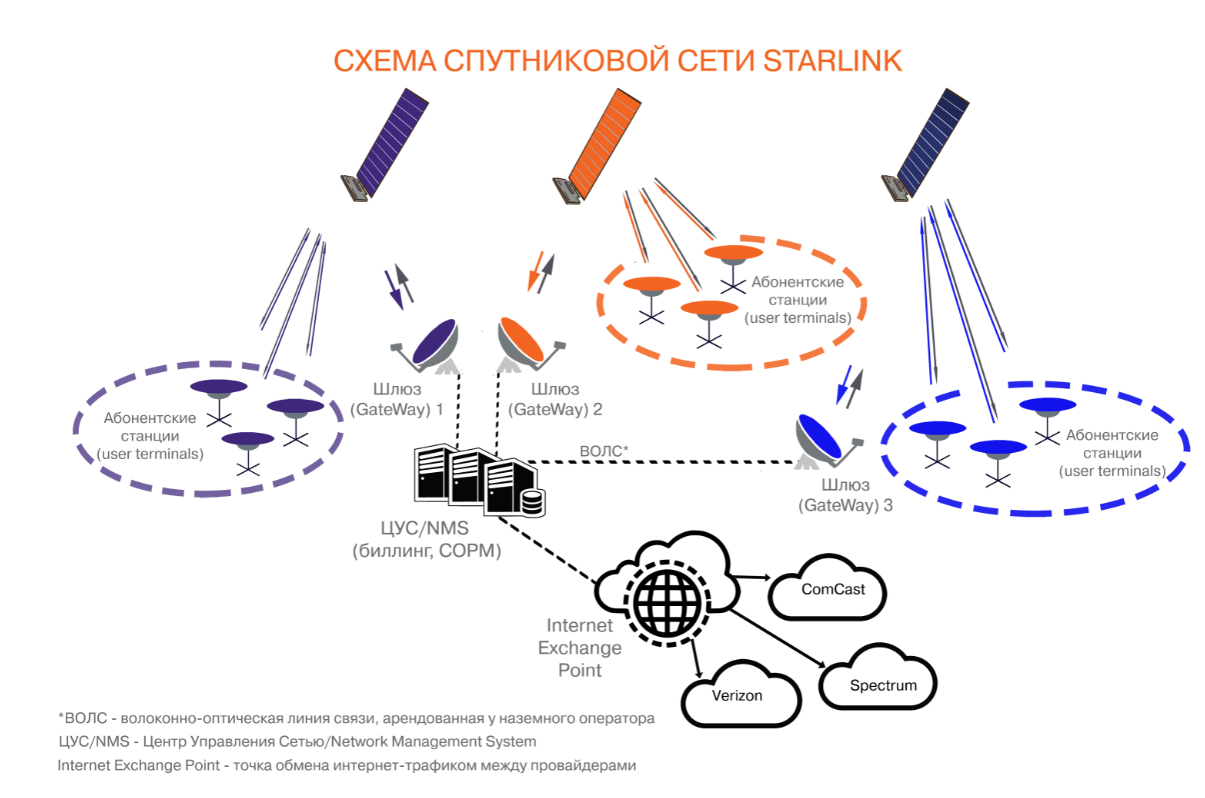
Приведенный ниже документ «Starlink Gateway V3 Technical Information 08-07-20» является актуальным и используется в США и за его пределами подрядчиками SpaceX при строительстве Гейтвеев. В документе указаны основные технические параметры антенны и приемопередатчика Гейтвея.
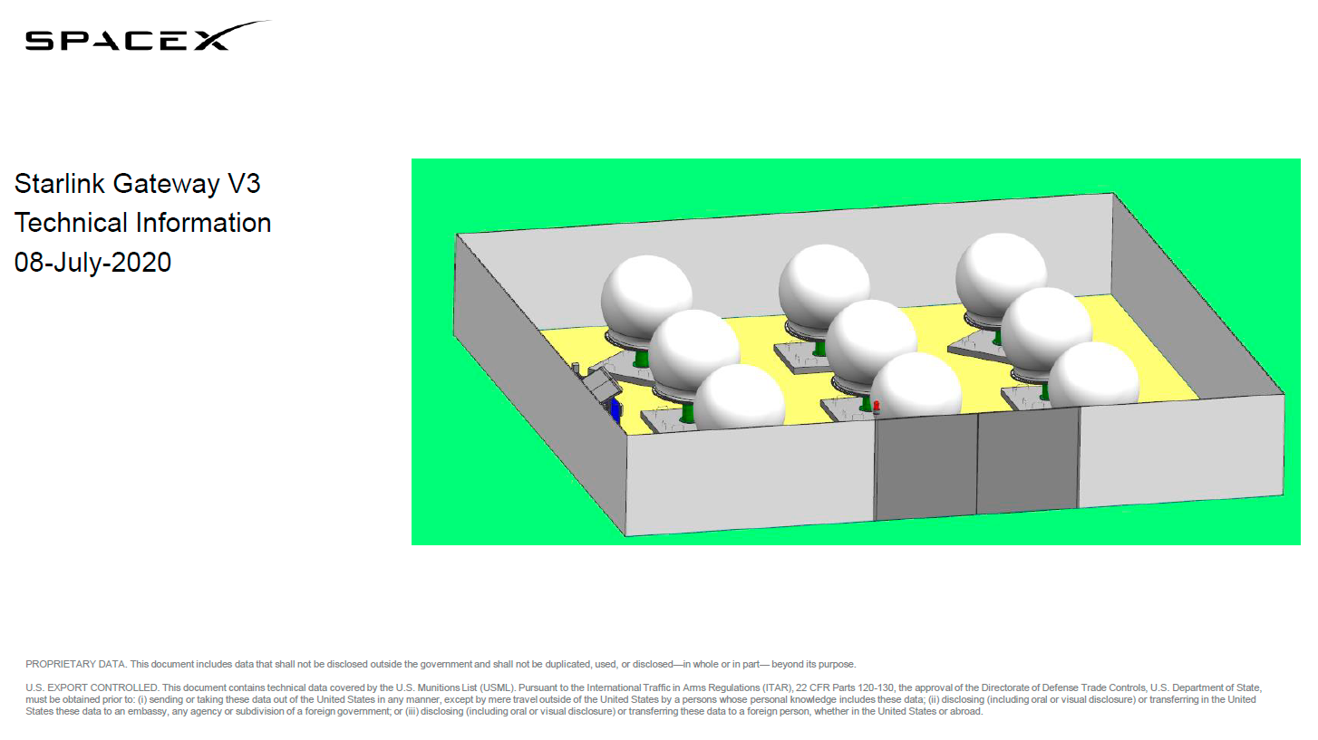
- Gateway V3 Summary
- System Specifications
- RF Overview
- Mechanical Overview
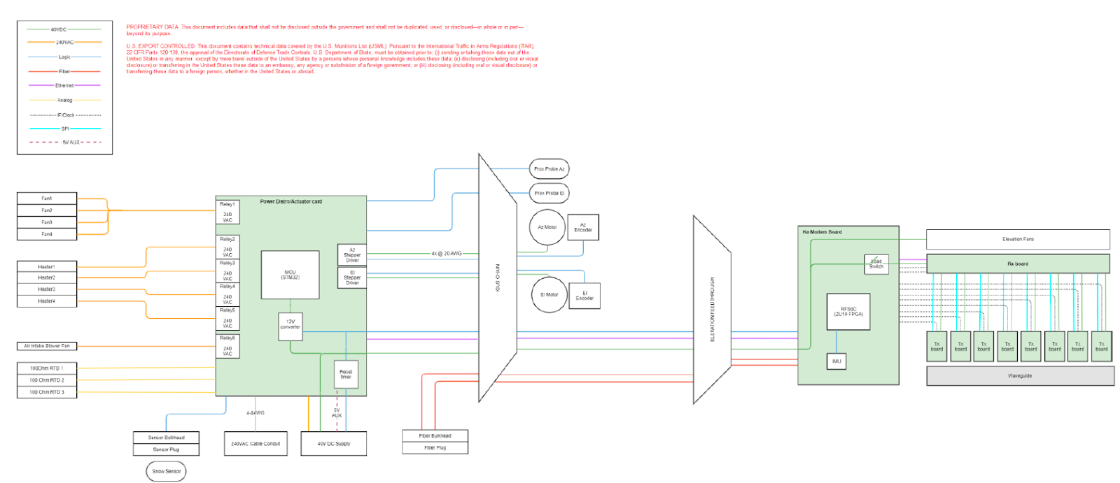
- Gateway V3 Block Diagram
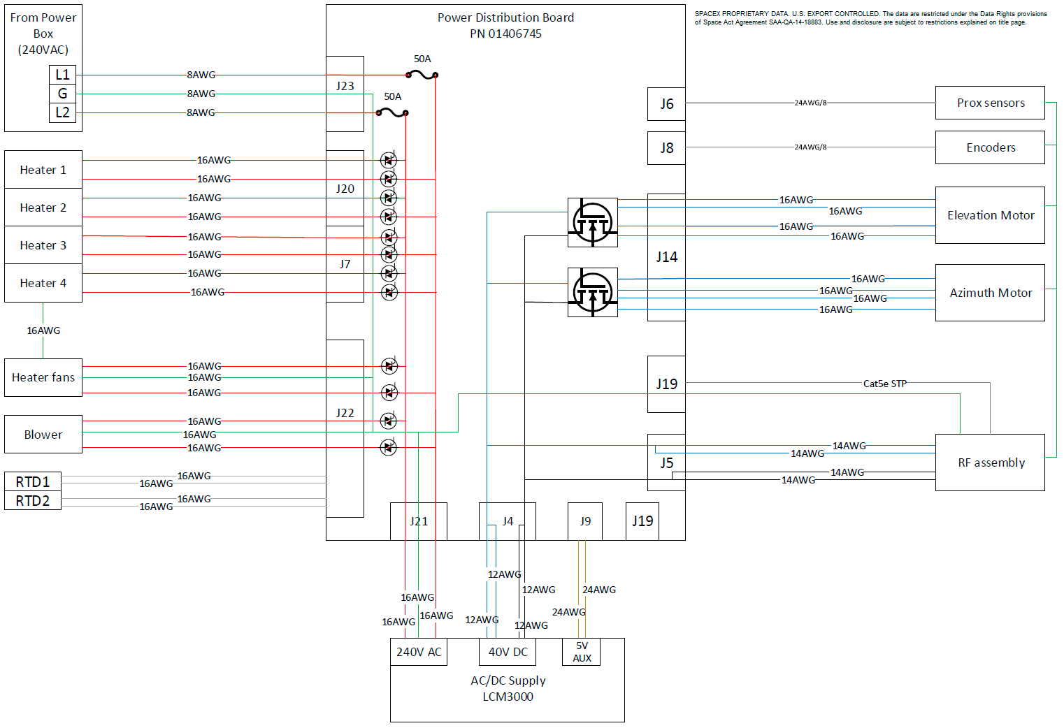
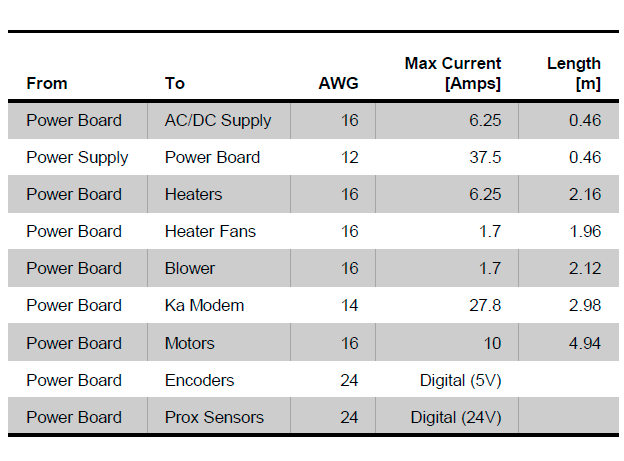
- Gateway V3 Wiring Diagram
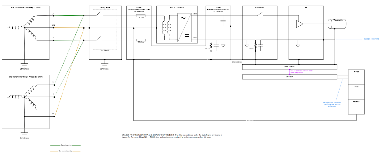
- Gateway Grounding Diagram
- Harmonized Shipping Codes (TBD)
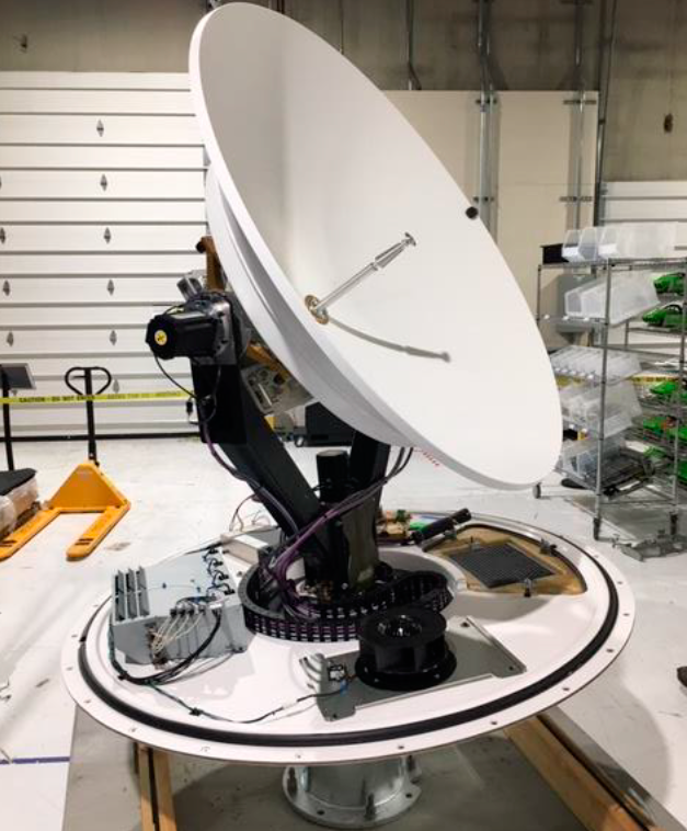
- Photographs
Gateway V3 Summary
- The Starlink V3 Gateway is a fully integrated Ka antenna and motion platform, assembled into a weather resistant
enclosure ( radome ).
- Gateways are custom steerable parabolic dishes that provide the high bandwidth data backhaul to our satellites.
Unlike the user terminals, the gateways are not placed at customers’ houses they are located behind fences at
telecom sites
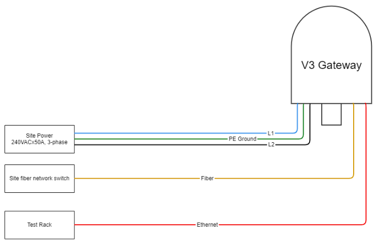
- The gateway is powered using 240VAC, 3 phase power and communicates to an external network switch through a fiber optic cable. An umbilical Ethernet connection is available for testing purposes, but will not be used in the field.
Inside the radome are heaters and a blower to control internal temperature (and humidity to some extent). Below is a simplified assembly level block diagram
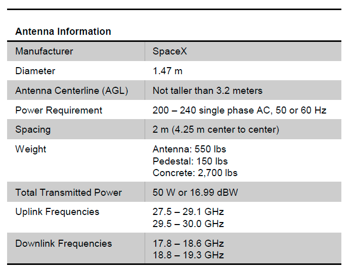
System Specifications
RF Overview
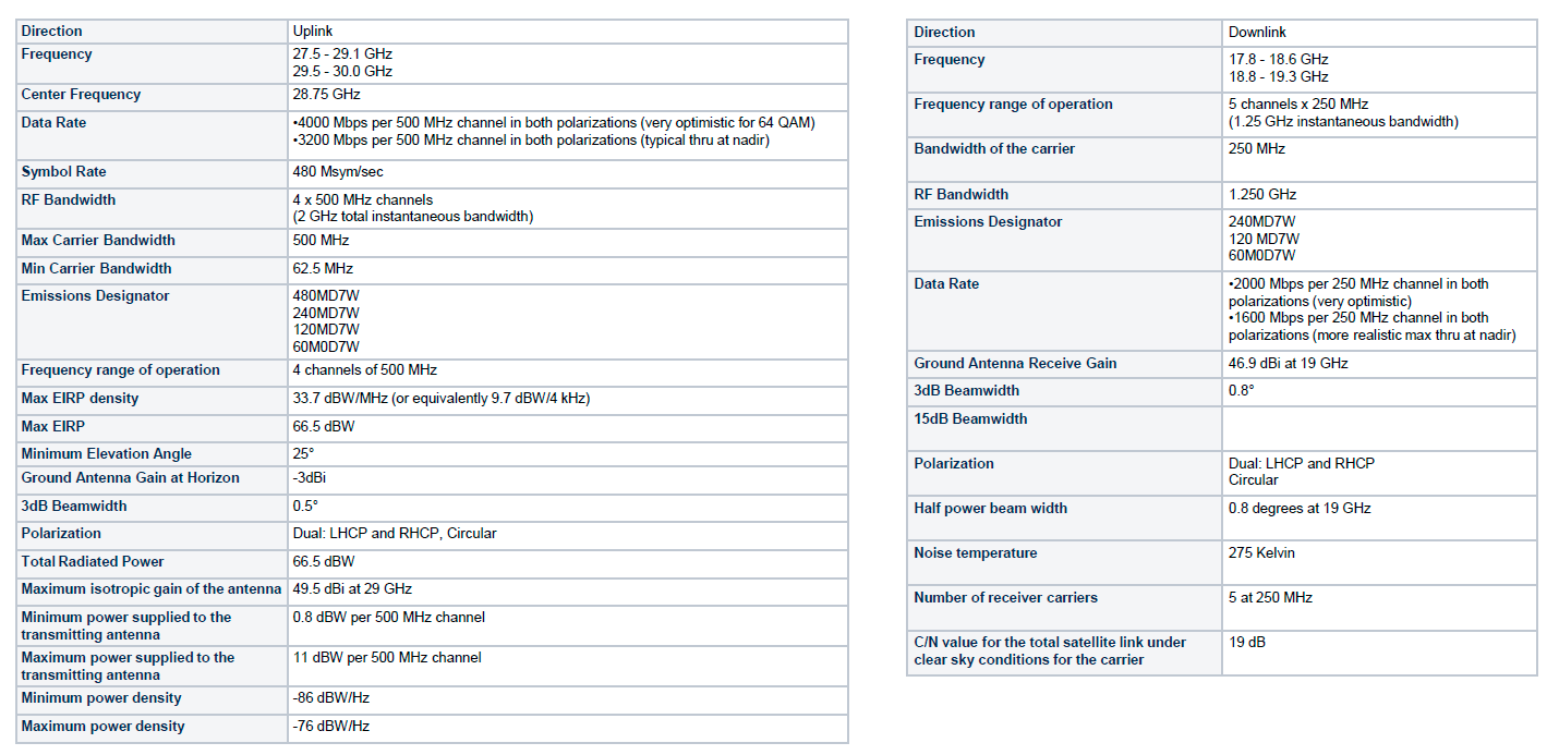
- The radiation pattern of the gateway is designed to be compliant with the
following specifications:
• FCC 25.209
• ITU S.580
- The spectral mask of the gateway is designed to be compliant with the
following specifications:
• ITU SM.1541
• ITU SM.329
• FCC 25.202
Mechanical Overview
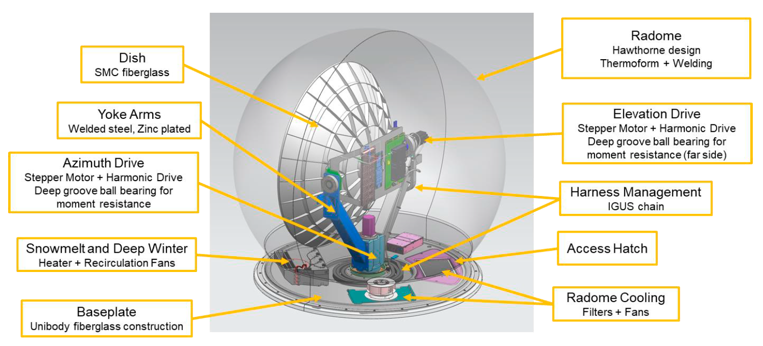
Gateway V3 Block Diagram
Gateway V3 Wiring Diagram
Gateway Grounding Diagram
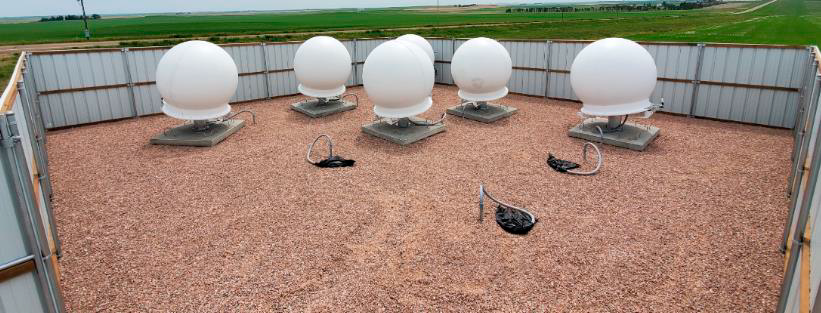
Photographs
Partial 1×9 Site Example
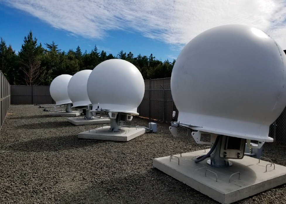
Partial 3×3 Site Example
Revision History
- 07/08/2020: Added RF overview slides.


