US489238A - Roundabout - Google Patents
Roundabout Download PDFInfo
- Publication number
- US489238A US489238A US489238DA US489238A US 489238 A US489238 A US 489238A US 489238D A US489238D A US 489238DA US 489238 A US489238 A US 489238A
- Authority
- US
- United States
- Prior art keywords
- rims
- cables
- frame
- roundabout
- driving
- Prior art date
- Legal status (The legal status is an assumption and is not a legal conclusion. Google has not performed a legal analysis and makes no representation as to the accuracy of the status listed.)
- Expired - Lifetime
Links
- 230000002093 peripheral Effects 0.000 description 7
- 239000000969 carrier Substances 0.000 description 5
- 238000010276 construction Methods 0.000 description 5
- 239000000203 mixture Substances 0.000 description 5
- 210000001503 Joints Anatomy 0.000 description 2
- 239000000725 suspension Substances 0.000 description 2
- 239000002023 wood Substances 0.000 description 2
- 230000013707 sensory perception of sound Effects 0.000 description 1
Images


Classifications
-
- A—HUMAN NECESSITIES
- A63—SPORTS; GAMES; AMUSEMENTS
- A63G—MERRY-GO-ROUNDS; SWINGS; ROCKING-HORSES; CHUTES; SWITCHBACKS; SIMILAR DEVICES FOR PUBLIC AMUSEMENT
- A63G27/00—Russian swings; Great wheels, e.g. Ferris wheels
Definitions
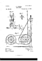
- Figure l of the drawings is a representation of the invention in side elevation.
- Fig. 2 is a front view.
- Fig. 3 is a side view of the driving gear.
- Figs. 4 and 5 are details of the belt tightener.
- Fig. 6 is a detail of the brake.
- Figs. 7 and 8 are details illustrating the construction of the hub.
- Figs. 9 and 10 are details showing the construction of the rims
- Figs. 11 and 12 are details showing the manner of suspending the carriers.
- This invention has relation toimprovements in roundabouts, and it consists in the novel construction and combination of parts as hereinafter specified.
- the letter A designates a circular wheel-like frame, carried upon a horizontal axis, and designed to revolve in a vertical plan e.
- the shaft or axle of the wheel is provided with bearings 19 in any suitable supporting frame B.
- the frame A is shown as consisting of the two parallel annular rings or rims O, C, of equal diameter and spaced laterally from each other, as shown. Said rims are supported from the hub or axial portions by the radial arms or spokes D, suitably connected and braced to insure proper strength.
- Connecting the rims O, C is a series of transverse bars or shafts E, located at intervals from each other and extending around the entire circnmference of the wheel or frame. From each of these bars is vertically suspended a suitable carrier or seat F by means of rods, links, or cables 1-1, 11, secured to said carriers or seats at their lower ends, and at their upper ends having loose hearings on the bars. As the wheel or frame is revolved, said carriers or seats are carried therewith, and by reason of their loose bearings on the bars 1),
- the distance between the rings or rims G, C is sufficient to allow the seats to swing between them and to pass therethrough, and the distance between the bars D, is also sufiicient to permit the seats to swing between them. If it is desired to provide a machine of a larger carrying capacity, an additional rim or rims may be provided, together with an additional series ofseats or carriers.
- each rim In the peripheral edge of each rim is a continuous surrounding groove e, in which runs one of the endless parallel belts or cables K. bles pass down on their respective sides and several times around the grooved wheels L, L, of the driving gear. They are held to the grooves in the rims by means of the idler pulleys or wheels Z, Z respectively.
- the idler wheels are hung in the boxes P, which are adjustable vertically in their supports P, by means of the screws 13, bearing in brackets 10 and engaging said boxes, whereby any excess of slack in the cables may be taken up to prevent their slipping.
- R designates a pulley on the main shaft of the engine, said pulley carrying a belt R which passes over a larger pulley R on the shaft of the driving wheels L, and by means of which they are driven. 0n the end of the main shaft is a balance wheel R and R is abrake shoe in engagement therewith, said shoe being operated by the bar 1'.
- each rim should possess sufficient strength to insure safety, and at the same time that they should be as light as possible. They are therefore usually made of wood, and constructed as follows:
- the body of each rim is composed of the two annular rings S, S suitably secured together.
- the grain of the wood forming these rings may run as straight as possible they are each formed'of the'short segments 3, the joints of the said segments in the two rings being so located as to overlap each other.
- To the outer surface of each of these rings is usually secured a thin veneerlike ring S as shown.
- .8, s designate two pieces secured on the rings S, S, and forming between them the groove for the cable.
- a thin strip .9 may be interposed between the rings S, S, and the pieces 5:, s, as shown in Figs. 9 and 10, said piece being secured to the rings S, S.
- This piece serves to break the joints between the said rings S, S and s, s, but it may however be omitted, in which case the latter pieces are secured directly to the frame.
- the hub portions T of the wheel in which the radial arms or spokes are secured are also usually of special construction, to insure proper strength.
- the shaft of the wheel usually consists of a squared beam '1", around which the hub portions are secured.
- the portion 15 of each hub, against which the ends of the spokes rest is shown as formed of four segments or sections secured around the shaft. Abutting against each end of this portion 5 is a disk U, formed of similar sections, the whole being bolted or otherwise secured together. Between these two disks are held the spokes,
- a roundabout comprising a circular rotary frame having the outer parallel rims supported from the hub portion, said rims consisting each of the following parts; the annular rings S, S, secured together and composed each of a series of lap jointed segments, the veneers S and the peripheral pieces .9, s forming the grooves for the driving cables, substantially as specified.
Description
4 sheets-sheet 1. W. SOMBRS. ROUNDABOUT.
(No Model.)
Padianted Jan; 3, 1893:
gwuawm mam;
(No Model.) 4 Sheets.-Sheet 2.
W.- SOMBRS.
ROUNDABOUT. No. 489,238. Patented Ja,11. 3, 1893.
8mm wi/lme/aow v/ [04am 12/ M (No Model.) 4 Sheets-Sheet 3.
w. SO-MERS.
ROUNDABOUT. No, 489,238. Patented Jan. 3, 1893.
(No Model.) 4 Sheets-Sheet, 4.
W. SOMBRS. ROUNDABOUT.
No. 489,238. Patented Jan. 3, 18-93.
Rms PETERS co, PHOTO-LIIHO.. WASHINGTON. n. c.
UNITED STATES PATENT OFFICE.
WILLIAM SOMERS, OF ATLANTIC CITY, NEW JERSEY.
ROUNDABOUT.
SPECIFICATION forming part of Letters Patent N 0. 489,238, dated January 3, 1893.
Application filed October 28, 1891. fierlal No. 410,110. (No model.)
To all whom, it may concern:
Be it known that 1, WILLIAM SOMERS, a resident of Atlantic City, in the county of Atlantic and State of New Jersey, have invented certain new and useful Improvements in Roundabouts; and I do declare the following to be a full, clear, and exact description of the invention, such as will enable others skilled in the art to which it appertains to make and use the same, reference being had to the accompanying drawings, and to letters of reference marked thereon, which form a part of this specification.
Figure l of the drawings is a representation of the invention in side elevation. Fig. 2 is a front view. Fig. 3 is a side view of the driving gear. Figs. 4 and 5 are details of the belt tightener. Fig. 6 is a detail of the brake. Figs. 7 and 8 are details illustrating the construction of the hub. Figs. 9 and 10 are details showing the construction of the rims, and Figs. 11 and 12 are details showing the manner of suspending the carriers.
This invention has relation toimprovements in roundabouts, and it consists in the novel construction and combination of parts as hereinafter specified.
In the accompanying drawings, the letter A designates a circular wheel-like frame, carried upon a horizontal axis, and designed to revolve in a vertical plan e. The shaft or axle of the wheel is provided with bearings 19 in any suitable supporting frame B.
The frame A is shown as consisting of the two parallel annular rings or rims O, C, of equal diameter and spaced laterally from each other, as shown. Said rims are supported from the hub or axial portions by the radial arms or spokes D, suitably connected and braced to insure proper strength. Connect ing the rims O, C is a series of transverse bars or shafts E, located at intervals from each other and extending around the entire circnmference of the wheel or frame. From each of these bars is vertically suspended a suitable carrier or seat F by means of rods, links, or cables 1-1, 11, secured to said carriers or seats at their lower ends, and at their upper ends having loose hearings on the bars. As the wheel or frame is revolved, said carriers or seats are carried therewith, and by reason of their loose bearings on the bars 1),
will at all times keep their vertical suspension whatever may be the relative position of the frame. The distance between the rings or rims G, C is sufficient to allow the seats to swing between them and to pass therethrough, and the distance between the bars D, is also sufiicient to permit the seats to swing between them. If it is desired to provide a machine of a larger carrying capacity, an additional rim or rims may be provided, together with an additional series ofseats or carriers.
An important feature of the invention resides in the driving gear, the arrangement of which will now be described. In the peripheral edge of each rim is a continuous surrounding groove e, in which runs one of the endless parallel belts or cables K. bles pass down on their respective sides and several times around the grooved wheels L, L, of the driving gear. They are held to the grooves in the rims by means of the idler pulleys or wheels Z, Z respectively. The idler wheels are hung in the boxes P, which are adjustable vertically in their supports P, by means of the screws 13, bearing in brackets 10 and engaging said boxes, whereby any excess of slack in the cables may be taken up to prevent their slipping.
Q, designates small idler wheels one on each side, which are hung in bearings at the rear of the driving wheels L, and serve to guide the driving cables into the grooves on said driving wheels.
R designates a pulley on the main shaft of the engine, said pulley carrying a belt R which passes over a larger pulley R on the shaft of the driving wheels L, and by means of which they are driven. 0n the end of the main shaft is a balance wheel R and R is abrake shoe in engagement therewith, said shoe being operated by the bar 1'. By cutting oif steam and applying the brake, the machine may be stopped almostimmediately. By this double arrangement of the driving cables a greater degree of safety is insured, inasmuch as should one cable break, or become so loose as to slip, the remaining one will still keep the machine in operation.
The application of the driving power as above described whereby the cables are caused to run around the peripheries of the outer rims of the frame, is preferred, if not These caessential to the successful operation of the device, for the reason that insomuch as the frames are usually made of large diameter, the circumferential series of seats are at a great radial distance from the center. Consequently the application of power at any point Within the circumference is not sufficient to operate the machine when heavily loaded. But by passing the cables directly around the rims between which the seats are suspended, the power is applied directly to the point where the work is to be done, and all danger of accident arising from the slipping or breaking of gear is obviated.
It is of course necessary that the rims O, C should possess sufficient strength to insure safety, and at the same time that they should be as light as possible. They are therefore usually made of wood, and constructed as follows: The body of each rim is composed of the two annular rings S, S suitably secured together. In order that the grain of the wood forming these rings may run as straight as possible they are each formed'of the'short segments 3, the joints of the said segments in the two rings being so located as to overlap each other. To the outer surface of each of these rings is usually secured a thin veneerlike ring S as shown.
.8, s, designate two pieces secured on the rings S, S, and forming between them the groove for the cable. By this construction a strong as well as durable ring is provided. A thin strip .9 may be interposed between the rings S, S, and the pieces 5:, s, as shown in Figs. 9 and 10, said piece being secured to the rings S, S. This piece serves to break the joints between the said rings S, S and s, s, but it may however be omitted, in which case the latter pieces are secured directly to the frame.
The hub portions T of the wheel in which the radial arms or spokes are secured, are also usually of special construction, to insure proper strength. The shaft of the wheel usually consists of a squared beam '1", around which the hub portions are secured. The portion 15 of each hub, against which the ends of the spokes rest is shown as formed of four segments or sections secured around the shaft. Abutting against each end of this portion 5 is a disk U, formed of similar sections, the whole being bolted or otherwise secured together. Between these two disks are held the spokes,
their inner ends abutting against the portion 15, and separated from each other by segment wedges 12.
Having described this invention, what I I claim as new and desire to secure by Letters Patent is:
1. In a roundabout, the combination of the parallel annular rims, their braces, and a peripheral series of cross ties forming suspension rods, the carriages suspended from said rods, the continuous grooves in the peripheries of said rims, and the double parallel driving'cables working in said grooves, substantially as specified.
2. In a roundabout, the combination of the parallel annular rims, the continuous grooves in the peripheral faces of said rims, the double paralleldrivingcables working in said grooves, and the series of carriages suspended between said rims and cables, substantially as specified.
3. The combination with the rotary, circular vertical frame, arranged to turn on a horizontal axis, and having grooves in its peripheral rims, of the driving gear for said frame, said gear comprising the double driving cables working in the grooves in said peripheral rims, and actuated by grooved wheels on the driving shaft, substantially as specified.
4. The combination with the rotary, circular, vertical frame, having the peripheral rims grooved-on their outer edges, of the driving gear for said frame, said gear comprising double endless cables working in said grooves, the grooved wheels L, L, carrying said cables, one pair for each cable, and carried by.
a common driving shaft, the idlers and tighteners for said cables, and the brake device, substantially as specified.
5. In a roundabout comprising a circular rotary frame having the outer parallel rims supported from the hub portion, said rims consisting each of the following parts; the annular rings S, S, secured together and composed each of a series of lap jointed segments, the veneers S and the peripheral pieces .9, s forming the grooves for the driving cables, substantially as specified.
In testimony whereof I affix my signature in presence of two witnesses.
WM. SOMERS.
Witnesses:
CLIFTON C. SHINN, H. F. COGILL.
Publications (1)
| Publication Number | Publication Date |
|---|---|
| US489238A true US489238A (en) | 1893-01-03 |
Family
ID=2558084
Family Applications (1)
| Application Number | Title | Priority Date | Filing Date |
|---|---|---|---|
| US489238D Expired - Lifetime US489238A (en) | Roundabout |
Country Status (1)
| Country | Link |
|---|---|
| US (1) | US489238A (en) |
Cited By (1)
| Publication number | Priority date | Publication date | Assignee | Title |
|---|---|---|---|---|
| US8641542B2 (en) | 2009-09-04 | 2014-02-04 | William J. Kitchen | Stationary track with gimbaled rider carriages amusement ride |
-
0
- US US489238D patent/US489238A/en not_active Expired - Lifetime
Cited By (1)
| Publication number | Priority date | Publication date | Assignee | Title |
|---|---|---|---|---|
| US8641542B2 (en) | 2009-09-04 | 2014-02-04 | William J. Kitchen | Stationary track with gimbaled rider carriages amusement ride |
Similar Documents
| Publication | Publication Date | Title |
|---|---|---|
| US489238A (en) | Roundabout | |
| US1295138A (en) | Troughing belt-pulley. | |
| US901175A (en) | Stone-sawing machine. | |
| US336407A (en) | Band-saw mill | |
| US186379A (en) | Improvement in velocipedes | |
| US548187A (en) | Half to edward c | |
| US396872A (en) | Vehicle-wheel | |
| US553468A (en) | Carousel | |
| US689521A (en) | Pulley. | |
| US492072A (en) | Feed-roller | |
| US514612A (en) | Unicycle | |
| US127174A (en) | Improvement in whirligigs | |
| US365037A (en) | Band-saw wheel | |
| US238579A (en) | Sheave | |
| US585696A (en) | player | |
| US722433A (en) | Bicycle-wheel. | |
| US402448A (en) | Sprocket-wheel | |
| US591027A (en) | wootton | |
| US820118A (en) | Amusement apparatus. | |
| US1334727A (en) | Pleasure-machine | |
| US446293A (en) | Band-saw mill | |
| US484524A (en) | Horse-power | |
| US499627A (en) | Sprocket-wheel | |
| US499724A (en) | Velocipede | |
| US269990A (en) | Traction-wheel |