Behind the Pretty Frames: God of War
- ⓘ Note
- 1.Wind (Compute)
- 2.GPU Particles (Compute)
- 3.Snow Mesh
- 4. Depth
- 5. Color
- 6.Forward+ (Compute)
- 7.Skybox/Cubemap
- 8.GI (Compute)
- 9.Emissive (& Late Particles)
- 10.Post Processing
- 11. Post Processing 2 (at the UI renderpass)
- 12.UI
- 13.Gamma Correction
- 14.Present
- Life of a Frame
- Random Notes
- Epilogue
- Related Readings & Videos
- Final Note
ⓘ Note
From the first publish of the article, there were many sections flagged with “red color”, as it was still in progress to tidy and write down (already had notes on papers & valid GPU captures). A lot of those sections made it finally day by day & piece by piece, and been filled with information and detailed imgs, but unfortunately there is still quite a few “red colored” sections around the article, not that much, but those remaining ones won’t get any more details or imgs, not because i don’t have the time, but because I’m not allowed to dig further in the game. The good news, those sections that i did not write, i have already investigated, so we might chat about any of them any time we taking a coffee together 🙂 .
With the release of God of War on PC, it was a must for me to give it a try. As an early 90’s gamer, i don’t mind at all re-playing a linear story game again & again. There is a treasure in there. So far my most played linear game is Max Payne (the 1st one) as i did play the entire game more than 15 times across multiple platforms. But still, my most played platform is PC. When i played GoW for the first time on the PS4 i did hope to own it on PC, i like to collect games & steam achievements in my library, and with that port/release this month, i decided to re-visit it. But this time, I decided to grab some working tools with me, as i was very curious about the engine/renderer behind that game when i played at the PS4 at release.
It is not a new thing for me, to re-play the games I love for an in depth behind the technology running the game, if i remember well, that syndrome started with Max Payne 3, and since then i tired many & many times to do that for other games that i liked and they rendered pretty, but unfortunately i never succeed to finish the essay. I take the captures, casually look at them, write down some notes, start taking screenshots, and then BOOM, i get busy in something else. The last 2 victims for that laziness was The Medium and Halo Infinite, perhaps i’ll finish them someday, release the draft post to public & free up the huge disk space their files occupying! Anyway, at this time, GoW is a whole different story, once i got the steam email about the release of the game, i took the decision to 1st replay it at least once for the achievement, and 2nd finish the rendering breakdown this time, and man, once i started in that, i kept hearing uncle Kratos saying “Boy” all the time!
There might be a part 2 for this article, as there are few things i remember from the first play on the PS4 that were interesting, but those are very far away in the story in far away realms, and will take sometime to reach. At first (here) we will breakdown & discuss the overall thing, the common ideas & features that are used and exist along the entire game, things that you can find at pretty much any frame at anytime during the game’s ~20h playthrough. And then (in part 2, not sure when) will be breaking-down few other unique things that are kinda extra, things that are exist during certain areas/realms, things that are not necessary to be found across the entire game. Let’s dive in!
NOTE: All images below, you can open in new page to see in full res (middle click or right click & then open in new page/tab)
Configs
I do have couple of PCs, captures been made with RTX 3070 & RTX 3080, and the game graphics settings are all set to Ultra. With that said the captures using the PC with AMD processor had always been hard to get, for some reason GoW would crash a lot if tried to get GPU captures using any method on the AMD PC, where in the Intel i9 PC it was totally stable. But I wanted to get multiple captures for same areas, just in case. But the main point here, is that I was running in Ultra settings, this is what could give different outcomes. Also I was running on display 1920*1200 and with HDR disabled.
Introduction
Surprisingly I found that GoW on PC is running on D3D11, which seemed a very vague choice for me & something i was not expecting at all. I understand that the initial release was around 2018, and at that time neither D3D12 nor VK was a common choice or common target to consider early, but still, it doesn’t’ matter for a GNM/GNMX based game. Yes release was 4 years ago but the game production itself may be started 4-5 years earlier, and as I always say that any console exclusive already have a version that runs internally on PC because it’s been developed and written on PC after all! So may be the GoW 2018 PS4 exclusive version had it’s Editor based on D3D11 on windows, and hence the decision came to leave it as it is, and use that as base for the windows port. At the end of the day D3D12 or VK will cost triple the time if not more. But still I was honestly expecting the 2022 PC port of the game to run on VK API, but it is what it is. Hopefully with an upcoming GDC there will be a more in depth talk about the work Santa Monica Studio put in that port. Let’s wait and see..
Behind the Frame
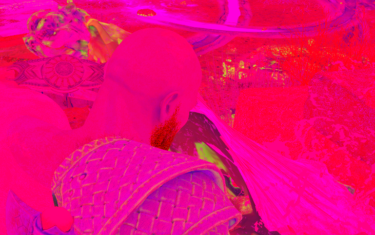
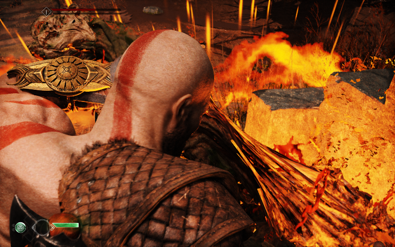
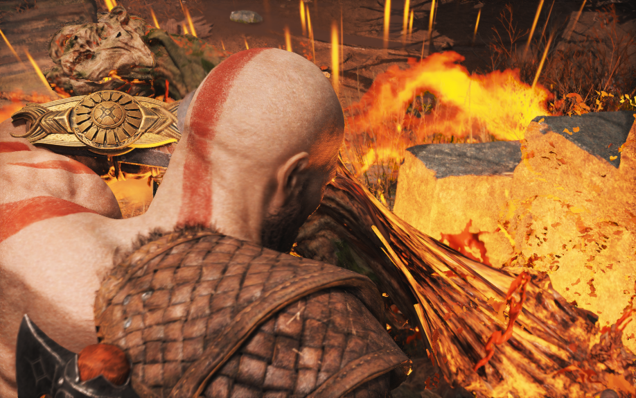
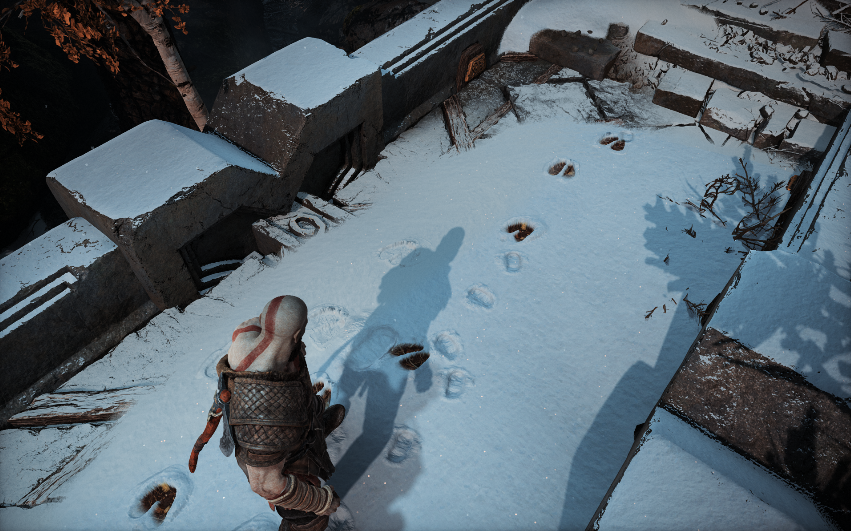
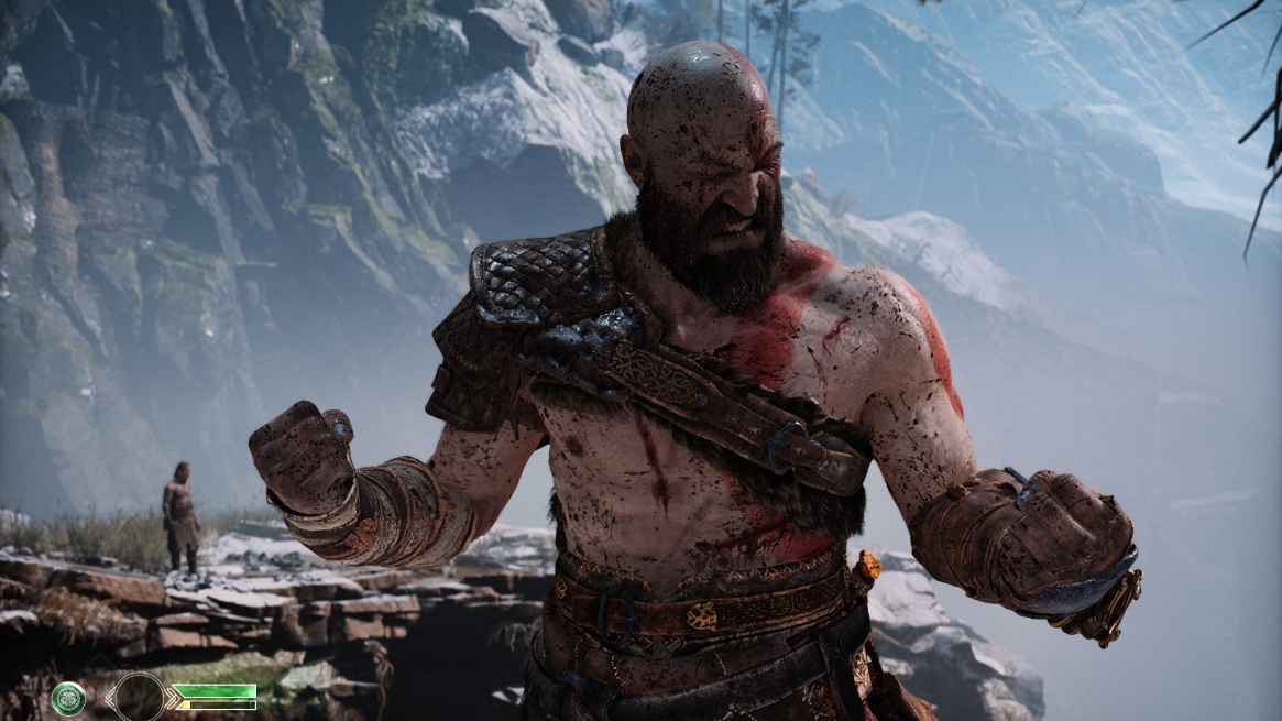
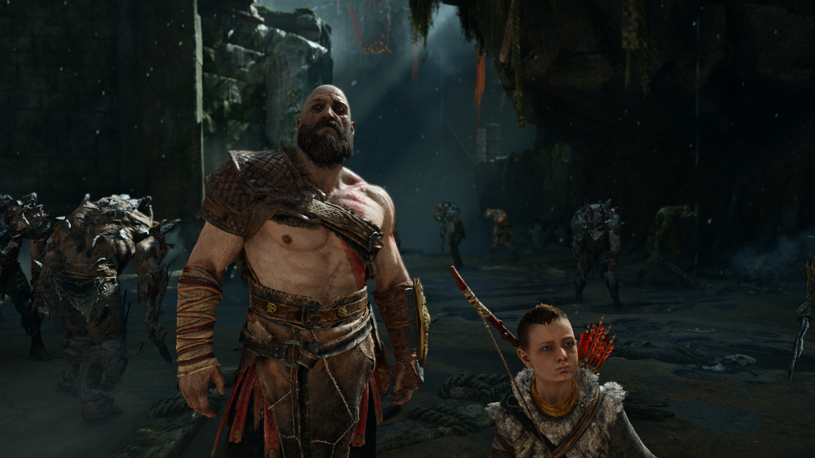
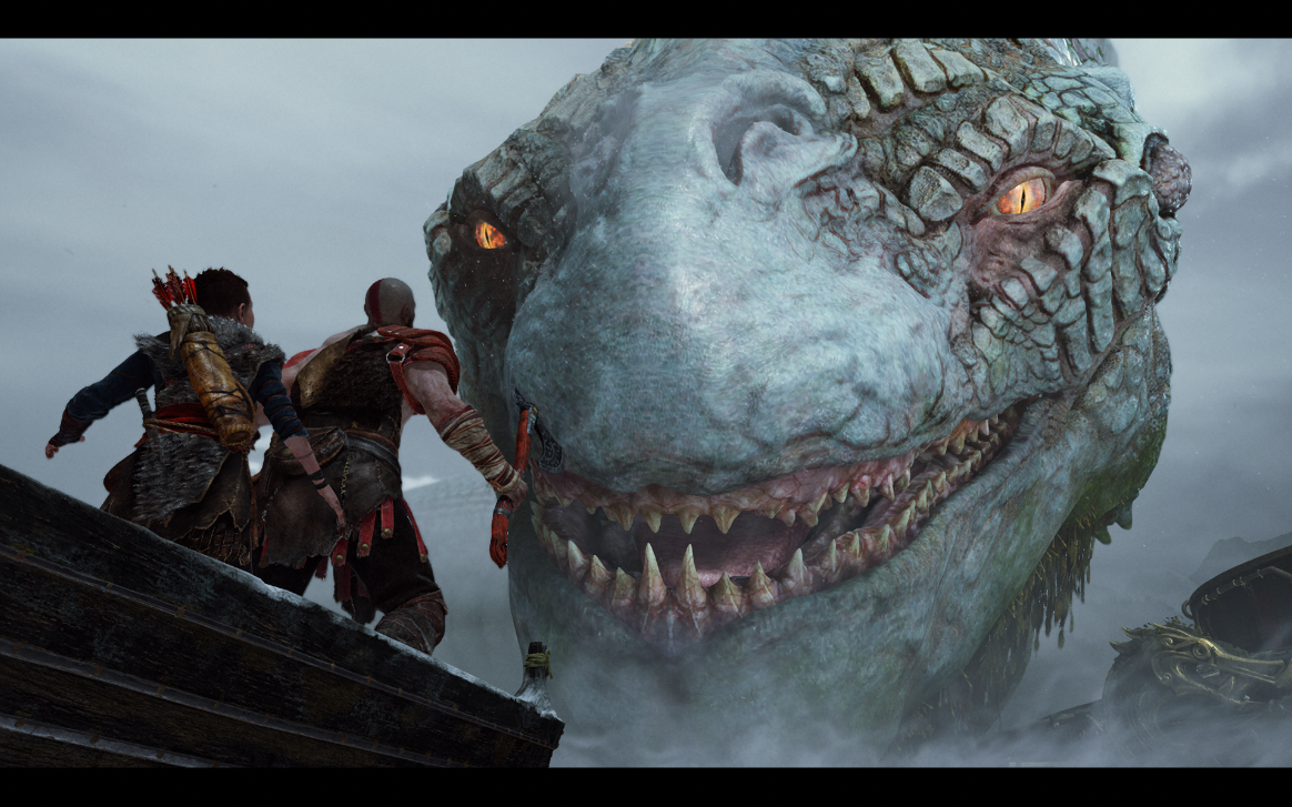
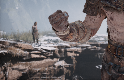
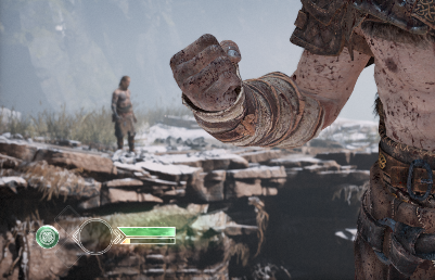
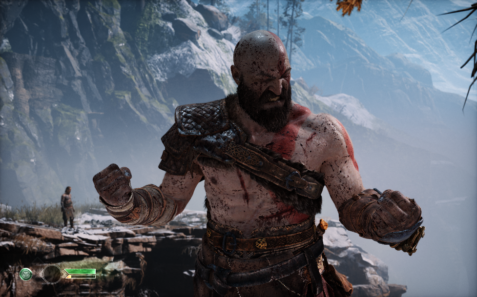
Screenshots below will vary between ~3 different frames, not all from single frame. But all those frames are identical in terms of what is going on under the hood, but i decided to do that to make things more clear when explaining them. For example when talking about particles, i’ll refer to a capture from a frame that focuses on particles, and when talking bout snow, i’ll refer to a capture from a frame that focus on snow. But for most none-specific things, i’ll be referring to the frame i love, the one i used for the thumbnail of this article. Here how a typical GoW frame being rendered in the order of execution
1.Wind (Compute)
Looks like Santa Monica guys are in love with compute & I can’t blame them, too much magic can be achieved in an outstanding speed & I’m not surprised, such an ultra beautiful game defiantly have a smart use of compute . In fact, it is not only Santa Monica, I believe all Sony 1st party studios are the earliest (and the best) when it come to utilizing compute in the most brilliant way on home consoles; Naughty Dog, Santa Monica, Insomniac, Sucker Punch,…etc. They’ve all prove & showcased brilliant compute based techniques in the past few years since the early days of the PS4.

The first compute dispatches invocation at a typical GoW frame takes place before any drawing cmds, oh boy, even before anything else. The frame literally start with a compute invocation, and that 1st compute always dedicated to the wind simulation, as if petty much everything down the frame would count on the current frame state of the wind sim, and I believe that’s the case here as we will see the order of the execution! Hair, particles, foliage/vegetation, cloth, audio emitters & other tiny gameplay elements are counting on the result of the wind simulation, and oh boy, wind in GoW is very sophisticated, i would recommend the GDC 2019 talk by Rupert Renard. Anyways, while i won’t be discussing how the wind actually simulated, but i guess shedding the light on what actually the data used to simulate the wind might be enough to give you a kickstart in understanding the essence of the technique. The wind data manipulated by that compute simulation is as follow:
Wind Data (Click to open)
| Data | Type | Size/Dimensions | Format/Components |
|---|---|---|---|
| Velocity(ies) | 3D Texture | 32*32*16 (16 slices) | R16G16B16A16_FLOAT |
| Turbulence | 3D Texture | 64*32*64 (64 slices) | R10G10B10A2_UNORM |
| Leave Instances | Structured Buffer | size varies | struct WindLeaveInst { float3 m_vPosWS; uint m_paramIdx; float3 m_vVelWS; float m_fGeoScale; } |
| Leave Parameters | Structured Buffer | size varies | struct WindLeaveParam { float m_fHighSpeed; float m_fLowSpeedDensity; float m_fHighSpeedDensity; float m_fWeightScale; float m_fBend; uint m_eRotationMode; float m_fStretchiness; float m_fUseWindAtPivot; float m_fSwaySpring; float m_fSwayDamping; uint m_eTreeMode; float m_fTreeBend; float m_fTreeWeightScale; float m_fTreeHeight; float m_fTreeLeafLag; float _unused0; } |
| Leave State | Structured Buffer | size varies | struct WindLeaveState { float3 m_vOffsetA; float m_fPhaseLerp; float3 m_vOffsetB; uint m_uIsReturnPhase; float3 m_vLeafSway; float3 m_vLeafSwayMomentum; float3 m_vTreeSway; float3 m_vTreeSwayMomentum; float3 m_vWindVecSmooth; float m_fPad0; } |
| Turbulence Data | Structured Buffer | size varies | struct TurbulenceData { float3 leafSwayLag; float bend; float3 offsetA; float useWindAtPivot; float3 offsetB; float phaseLerp; float3 densityLevel; float stretchiness; float3 densityLevelBlend; float treeBend; float3 rotationPivotMask; float treeHeight; float3 treeSway; float treeWeightScale; float3 leafSway; float leafWiggleScale; float windAdjustScale; float swaySpring; float swayDamping; float pad0; int _debugNoNoise; float _debugUserParam1; float _debugUserParam2; float padDebug; } |
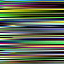
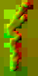
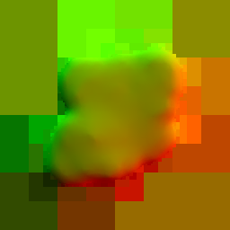
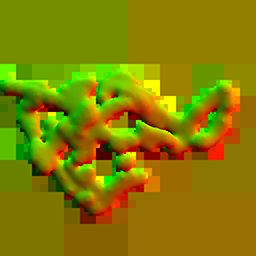
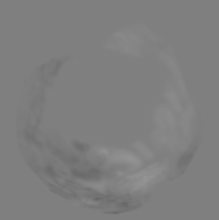
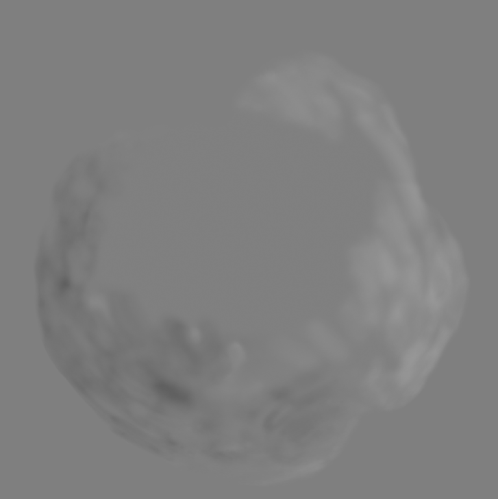
The core of the wind simulation is a the 3d textures that are a representation of a 3d volume/grid in the game world. A single slice of that 3d texture would look like something like that.

Each pixel in that slice represents a float3 that is either a turbulence value or velocity value at this grid cell in the world. A grid cell or a pixel representation in that 3d texture is measured as 1^meter3 in the game world. Regarding the tiny texture above, this is how it looks in the GPU and how the game reads it, but for more human readable and clear format, that slice of the 3d texture would look like that (if zoomed without any interpolations)

But all in all, pretty much every resource for that compute is created with both flags D3D11_BIND_SHADER_RESOURCE and D3D11_BIND_UNORDERED_ACCESS.
For further details about how the actual wind simulation math in compute itself works & possible some code snippets, check the GDC talks linked by the end of this page.
2.GPU Particles (Compute)
The 2nd group of compute dispatches takes place before any drawing cmds as well (same as wind), and it happens just right away after the wind simulation compute (make sense, everything counting on the wind sim output). This one is for the GPU particles simulation, and it seems that nearly all the particles i was able to spot in the course of 100GB of gpu captures; are GPU emitters. The GPU compute for the particle systems simulation varies based on the current frame complexity in terms of particle systems/emitters and their types variations. So far i was able to spot from 1 up to maximum of 3 different compute groups of dispatches for GPU particles. And a rule of thumb, in GoW, there is always particles in the screen, even if you can’t see them! Even if you’re in the main menu (make sense it’s UI rendered on top of a 3d map) or inside a gameplay menu, modifying your armor or upgrading you skill-tree, there are GPU particle compute invocations executed…ALWAYS!
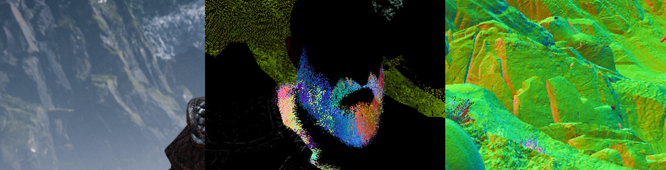
Particles in those computes are taking mostly data from the previous frame, as there isn’t much ready already for them to use. The entire previous frame GBuffer is used as an input for the GPU particles compute, this means we’ve access to previous’s frame depth, base color, normals, properties (AO, metallic, roughness/gloss), scattering, emissive. I’m not quite sure why all that are fed to the compute, i would have expected depth and probably normas only needed to run the GPU particles simulation, but there might be other reasons or use cases that require color and properties.
Previous frame’s GBuffer fully passed to compute
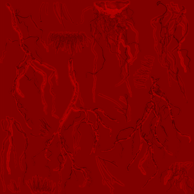
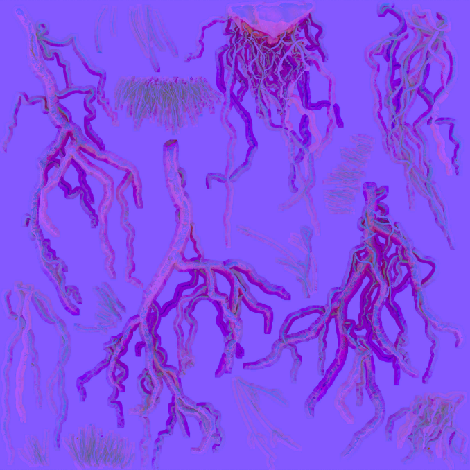
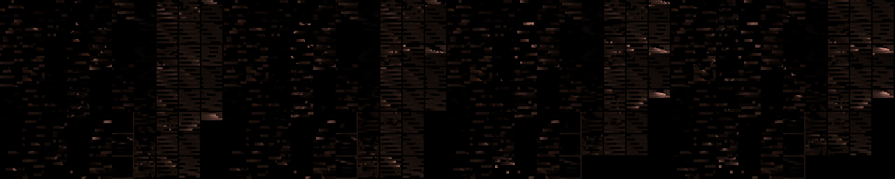
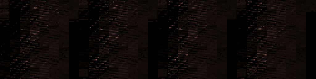
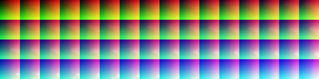
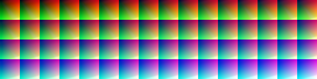
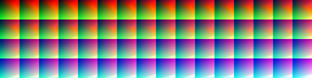
Another thing essential for the GPU particles, which is the wind data. The wind compute which ran earlier outputs a volume texture which is needed for the particles as well (this is a display for all the 16 slices of the 32*32*16 volume texture form the wind’s compute)

Apart from the GBuffer & wind, some structs passed to the compute, those are holding all the particle system properties, as well as the GPU particles emission job description. What happens in the compute shader with those values are beyond the scope of this article, but i’ll leave the particle data here as well, so it can give a quick glimpse of what been set and what is needed to run the simulations.
Particle Data (Click to open)
| Data | Type | Size/Dimensions | Format/Components |
|---|---|---|---|
| GPU Particles Emission Job Description | Array of Structured Buffer Max of 5000 elements | size varies | struct ParticleGPUEmissionJob { uint batchIndex; uint systemIndex; uint count; uint dstOffset; uint srcOffset; uint emitterType; uint interpType; float emitStart; float emitInterval; float batchAge; float timeStepInv; float quadInterpStart; float initialDistance; float frameDistance; uint decayEmitRandomStart; uint decayMaxCount; uint decayEmissionBufferOffset; uint decayAtomicCounterIndex; float decaySampleSpread; uint dupBatchIndex; uint dupCount; float dupAgeDiff; uint cFlags; float3 cDirection; float cSpeed; float cSpeedRandom; float cSpread; float cSpreadRandom; float cDistanceMin; float cDistanceRange; float cVelAwayFromCenter; float cVelAwayFromAxis; float cVelAlongAxis; float cVelDirectionalSpeed; float cVelAroundAxis; float cVelRandomDirection; float cVolumeSweep; float cSectionRadius; float3 emitPosition0; float3 emitPosition1; float3 emitPosition2; float3x3 emitOrientation0; float3x3 emitOrientation1; float3x3 emitOrientation2; float3 emitVelocity0; float3 emitVelocity1; uint _pad0; uint _pad1; } |
| Particle System Data | Array of Structured Buffer Max of 3000 elements | size varies | struct ParticleGPUFieldData { float3 position; float attenuation; float3 direction; float maxDistance; float magnitude; float _pad0; float _pad1; float _pad2; } struct ParticleGPUAttributeData { float start; float end; uint type; float alpha; float jitter; xint pad[3]; } struct ParticleGPUSystemData { float4x4 cSystemToWorld; uint cameraID; uint cDrawArgStart; float4 textureFlipbookVecs[10]; float3 cSpriteCenter; float3 cSpriteSize; float3 cSpriteSizeRandom; float2 cUVScale; float2 cUVOffset; float2 cUVScroll; uint cRibbonUVMode; float cTimeStep; uint cFlags; float cLifeTime; float cLifeTimeRandom; float cFogDensityStrength; float cAge; uint systemRandom; uint cAlignMode; uint cSecondaryAlignMode; uint cBlendMode; float cAngleFadeRate; float cSoftDistance; float cSoftDistanceInverse; float cVelocityScale; float cVelocityScaleClamp; float cExternalScale; float cSpriteRotation; float cSpriteCameraOffset; float cStaticTwist; float cTwistSpeed; uint cTwistDirection; float cMaxExtent; float cColorModulate; float cColorRandom; ParticleGPUAttributeData cParticleColorBlend; float4 cColorTintModulate; ParticleGPUAttributeData cNormalMapIntensity; ParticleGPUAttributeData cOpacity; ParticleGPUAttributeData cOpacityTexturesExponent; ParticleGPUAttributeData cScale; float cCameraScaleStartDistance; float cCameraScaleStartValue; float cCameraScaleEndDistance; float cCameraScaleEndValue; float cCameraOneOverEndMinusStart; uint cFlipbookPageCount; float cFlipbookPageCycle; float cNearCull; float cFarCull; float cNearFade; float cFarFade; ParticleGPUAttributeData cDrag; float3 cGravity; ParticleGPUAttributeData cGravityIntensity; ParticleGPUAttributeData cWindInfluenceOverLifeTime; float cMinDistance; float cMaxDistance; float3 cTurbulenceFrequency; float3 cTurbulenceAmplitude; float3 cTurbulencePhase; float3 cTurbulenceScrollSpeed; ParticleGPUAttributeData cTurbulenceIntensity; uint cActiveFields; ParticleGPUFieldData cFields[4]; float cNewtonMinDistance; float cCollisionBounciness; float cCollisionBouncinessRandom; float cCollisionRadius; float cDepthCollisionAgeThreshold; float cDepthCollisionThreshold; float cPlaneCollisionHeight; float3 emitterPosition; float3 emitterVelocity; float3 velocityDirectionWorld; float3x3 emitterOrientation; float emitterDistance; float cMFXEventProbability; uint4 ramp1Indices[2]; uint4 ramp3Indices; uint4 ramp1Constants[2]; float4 ramp3Constants; } |
| Ramp Data | Array of Structured Buffer Max of 4096 elements (not for sure) | size varies | struct ParticleGPURamp1Data { float multiplier; float offset; } |
Where the particles are fully GPU, and the entire simulation is done on the compute, but the particles systems have a tiny fraction that involves, which makes them referred to as CPU emitters. The CPU emitter is global data, the can be shared between the GPU particle system & the rest of the game (that is not necessarily accessing GPU data). This CPU tiny bit of data of the particle systems looks like that
CPU Emitter Data (Click to open)
| Data | Type | Size/Dimensions | Format/Components |
|---|---|---|---|
| CPU Emitter Particles | Array of Structured Buffer Max of is unknown! | size varies | struct ParticleGPUData { float3 position; float3 velocity; float3 axis; uint _pad0; uint _pad1; uint _pad2; } |
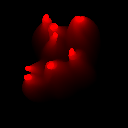
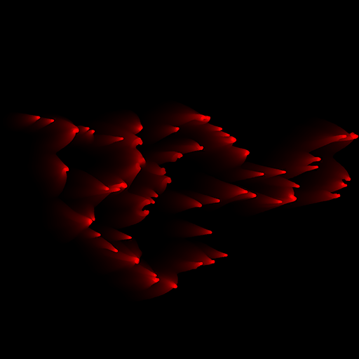
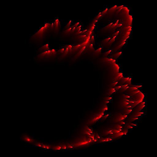
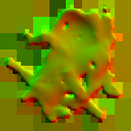
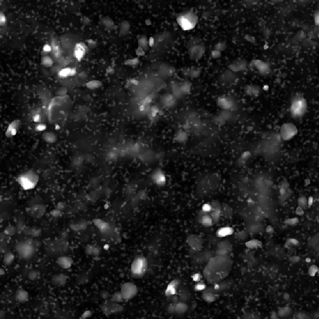
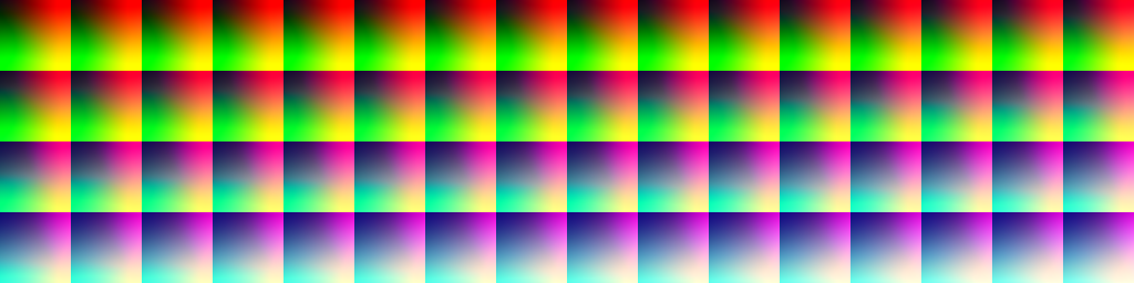
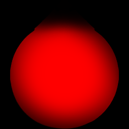
After the compute magic happens, we end up with a punch of particle positions/transform data. Those are most likely stored in a form of a ramp texture, where each pixel is holding the info for one particle ( i assume). This texture looks like something like that
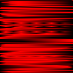
At the end, when the time comes to draw the color pass (the section number 5 below) this ramp texture of particle transform data, is used to draw the particles/quads (DrawIndexedInstancedIndirect) to their correct position resulted by the compute.

Keep in mind, i mentioned we draw at section 5, but this is not the only time we draw particles. It seems that we do draw more particles almost at the end of the frame (before post processing), but this later time is for particles with emissive values. So you can say it’s emissive pass sort of.
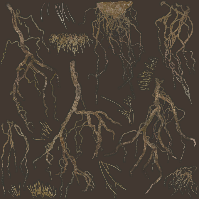
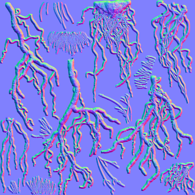
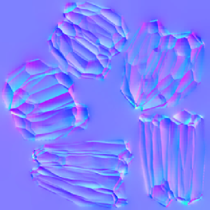
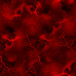
The draw process as mentioned is done in form of quads, but those quads are usually well textured with pretty normals, alpha-threshold, distortion textures (different cloudy textures for different variations) that makes them pump with life and look like 3d


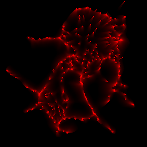
1st row examples of alpha thresholds & 2nd row examples of normals
For further details about how the compute is using this data to simulate the particles on the GPU, or what new features Santa Monica Studio brought to the table, go to the GDC talk linked by the end of this article.
3.Snow Mesh
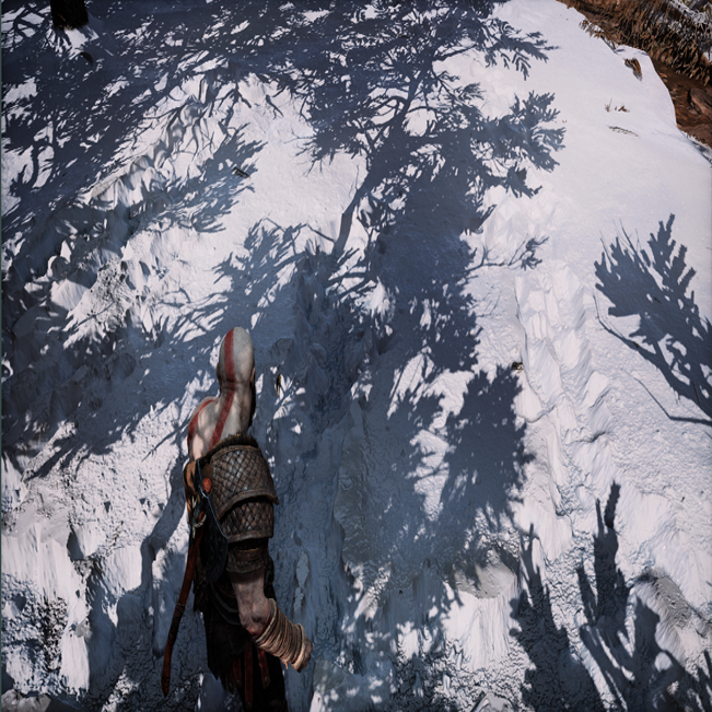
As it is always expected in such a type of game, that the first draw cmd will be for the terrain. But that is not exactly the case here, it seems that the first few draw cmds are for the snow coverage layer of the terrain, not the terrain itself. To make it easier to follow up, i used a different capture for this, I tired as much as possible to walk with uncle Kratos back and forth to type the letter M that turned out to look more like an E.

Snow mesh Draw
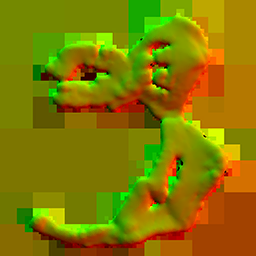
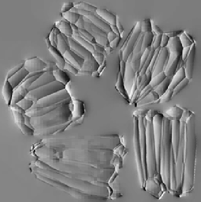
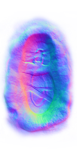
The snow mesh is drawn at first, it looks like sort of a pre-defined mesh piece that represents area that will be covered with deformable snow. The mesh from a bird’s eye view looks like something like that one below. it is of course a different piece of mesh per area. I assume that whole in the center is where Kratos’s home is.

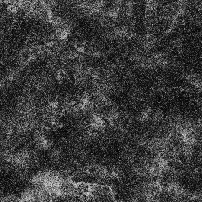
That mesh is using a bunch of cloudy-procdural-like BC5_UNORM and BC6_UFLOAT textures for the heights and flowmaps.


Note: that Flowmap 1*1 texture is used many times, here it is used probably as a brush for the painting process below (probably), but later on, the exact same texture been reused for many other things such as shadow and the GI. So it is not an exclusive texture for the purpose of the snow mesh shading.
Offscreen Painting (FS & Compute mix)
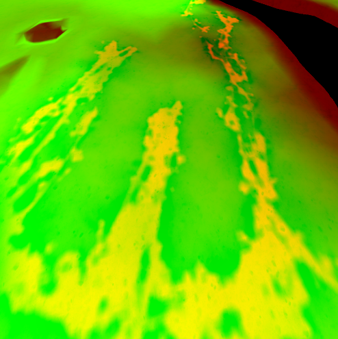
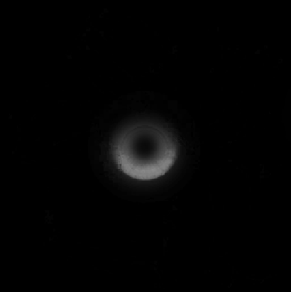
And once the mesh is ready, then the snow deformations starts which takes place in multiple sequential renderpasses, the render target of the snow deformation is being drawn-to based on the player current position (if in a snow covered grounds). Draws being made in a strangely sized R16G16B16A16_FLOAT render target that is 384*384 for some reason!
And then that 384*384 texture (the one with solid black) is passed to a compute to apply the heights to that path drawn by Kratos (based on the center of the the drawn strokes), so we can use those heights to deform the mesh properly without having a very steep edges. The final deformation render target (the one with yellow) resulted by the compute is a R16G16_FLOAT with the size of 1024*1024.


The choice here leaves me with a question of why not use the same format for the drawing render target, why use 4 channels while needing two only at the end? In fact the drawing render target is filling only the R channel, leaving the GBA totally black. So I would say this is a good area of possible optimization.
Previously when spoke about the 1*1 flowmap texture, I did say “probably” it is used to draw to the snow deformation RT. I said “probably” because I did notice that there were and entire color pass with a set of simple sphere draws (squashed & stretched) been executed to the positions of Kratos and those might be used to paint that deformations RT (the early one, the black & red one). But at the same time, according to one of the GDC talks, Sant Monica used to place spheres at the locations of Krato’s feed in order to affect/impact the foliage. So it could be those spheres exist for double use.
Once the compute is done, the rest is usual draw to mesh, using a bunch of textures to add more details and randomness to the player path on the snow mesh.
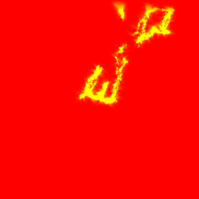


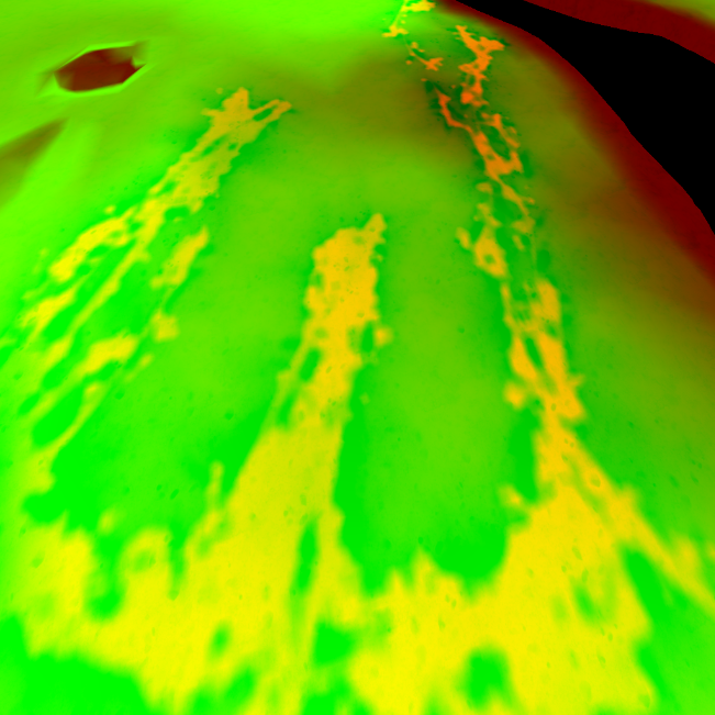
As mentioned at the start of this section, that the snow deformation happens multiple sequential renderpasses. Those are total of 3 color passes. So to eliminate any confusing here are what their use in the order of execution:
– 1st color pass will be dedicated to draw the player path on the deformations RT
– 2nd color pass will be dedicated to updating the deformation RT to have “height” values
– 3rd color pass will be used to draw that height RT texture(project it) in Screenspace to the snow deformation mesh.
So in order, those are the 3 output of those passes
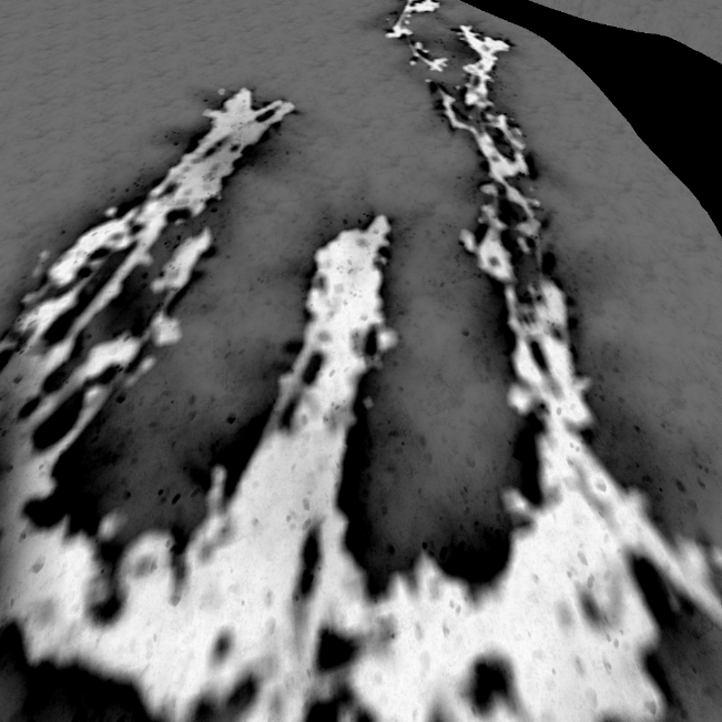
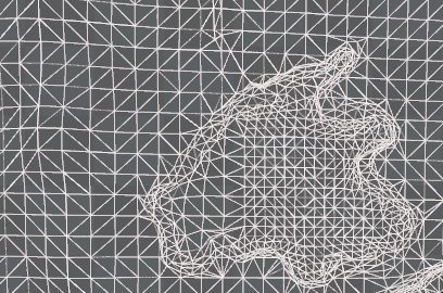
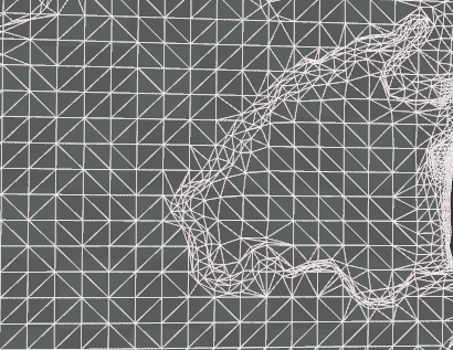
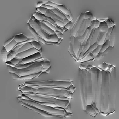
It is worth mentioning that the deformation process of the snow involves adaptive tessellation of that piece of geometry. And as tessellation works, add more when we are near with the view or use that area. Here are example of two different captures for the exact same area, and in each there is a different amount of tessellation applied to the snow mesh based on the camera view distance of Kratos at the time of the capture.
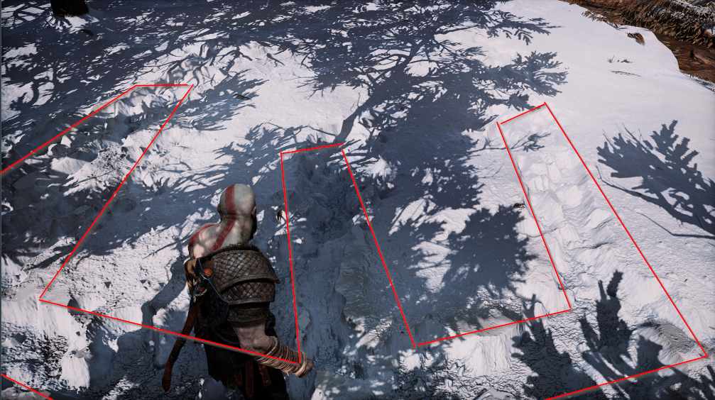
and before we end the discussion of the snow, yet every other game with similar snow would be doing it like that, nothing more, but what i was able to find that the core of the technique that makes the snow looks really great and stand out in GoW, is the use of Screen Space Parallax technique (using the result of the 3rd color renderpass, that yellow-ish green-is render target).
Parallaxing sauce is all what is needed for that pretty snow cake! You can easily spot the parallaxing visual artifacts/issues if put the view in a bizarre angles which usually can be achieved in photomode not at playtime.
So if we’re using the Screen Space Parallax method, which is enough to give believable visuals. Why would we need the tessellation? Well, only the wireframe can tell for that..or at that case, only the wireframe can LEAVE US WITH MORE QUESTIONS!
As you can see there is not a single tessellation effect happening at the snow deformations areas, despite the fact that the mesh itself when captured from the GPU alone as a 3d mesh, had tessellation in the screenshots previously. But here in a runtime video of the wireframe we see the snow mesh topology never changes and never updates. So this could be one of few things:
1. Yes there is tessellation happening, but it is compute tessellation (some companies do that), and hence it might be hard to capture in the wireframe rendering mode in the video.
2. The tessellation technique was used at some point, and abandoned and the snow deformations ONLY counting on the Screen Space Parallax. And what we see in the 3d mesh captures (the screenshots for gray mesh above) are remains of that, and not necessarily in actual use. And what makes me biased more towards this idea, that the tessellation for that mesh is not really “increased” in a very dense way to allow for mesh deformations, in fact it never tessellate in & out in levels the way adaptive tessellation usually works (check the example below). As you can see the screenshot above (gray mesh) is the maximum tessellation i was able to capture, and yet, this is never enough to make a believable path in the snow, it’s just a single level up (*2) for handful few polygons of the mesh, where multiple levels required to deform properly things like snow, water,…etc.
Adaptive Tessellation example captured in the same Wireframe Viewmode
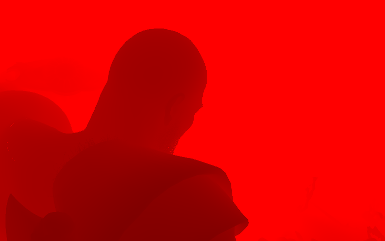
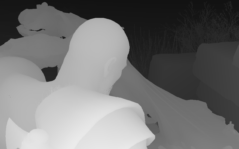
4. Depth
A standard draw of all geo to a D24S8_TYPELESS. Nothing fancy

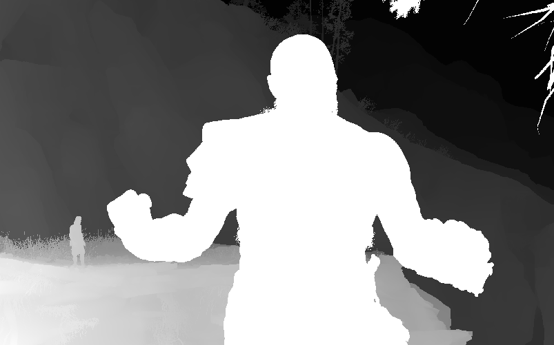
And of course things like particles is not included in the depth-only, as so far we only’ve calculated the GUP particles sim, but didn’t draw any. Particles will be drawn very late in the frame and they need depth to be drawn anyways, so it make perfect sense to not be present in the depth/stencil .So, from another capture that has some GPU particles, the depth-only would look like that
5. Color
Rendering in GoW is Deferred+, which means that the rendering will be going through few known phases. We’ve two main color passes, as well as couple of compute in-between.
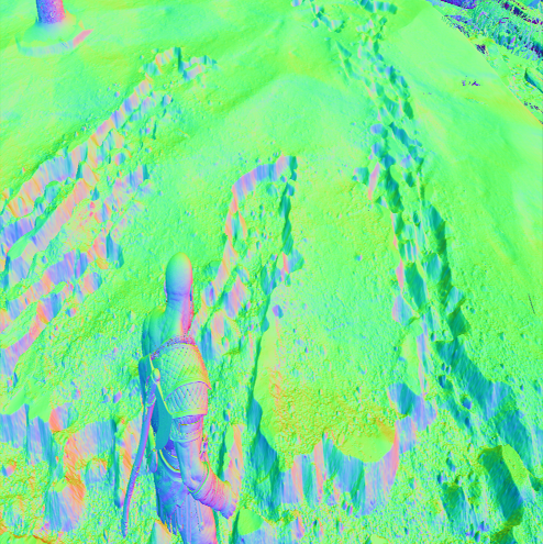
Main Color (5 RT + Dpth)
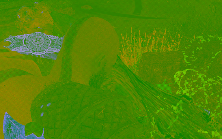
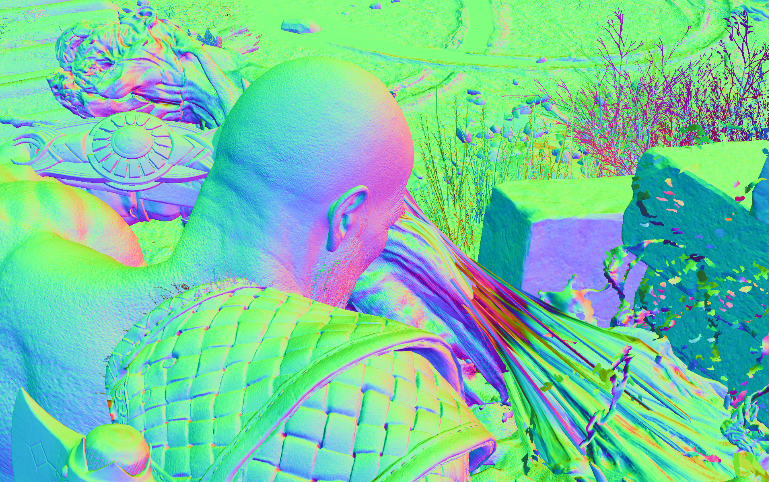
A pretty standard PBR, except it’s Specular Glossiness workflow instead of the commonly used nowadays Metal Rough worfkow. All meshes are for granted have a diffuse, normal, gloss & scatter. But not all meshes have a AO, Opacity, Emissive, Alpha textures.
Most of the textures are used to their maximum, the alpha channel is utilized most of the time for other purposes, where for example the AO texture is utilizing the RGB for different purposes where only a single channel would be enough.
Now, where all this would seem pretty standard or common. But there are an area of question or improvement according to my personal taste. The Gloss texture is using the R channel only (as it is shown very red-ish) but at the same time it’s a 4 channels texture. At the other hand, the AO texture is using the RGB channels, and the A is always left full plain white. Both textures are 1024*1024, so wouldn’t it be more beneficial to use the A channel of the AO to store the Gloss R’s channel (or vise versa), and save a full 1024*1024 *4 channels per mesh? Both, final game on disk and frame data in memory will defiantly make a good use from that.
Another way is to utilize more of the single channel formats when needed, but usually in a well made game like that, when i see similar cases, i tend more to believe that things are made for a reason. So when we see something like that, its probably implies that at some point during the production the 3-4 channels were in use per texture, and things changed down the road or before shipping. Who knows…I can’t tell, but I can predict ^_^
Another Example of a mesh that uses a different set of textures (Opacity, Emissive & Alpha) with a different variation of a PBR material/shader is the eyes.
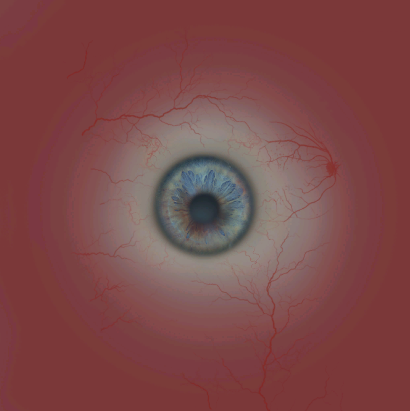
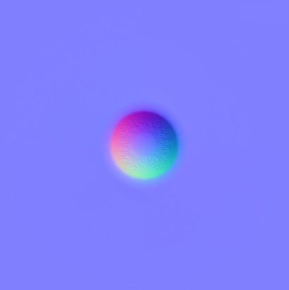
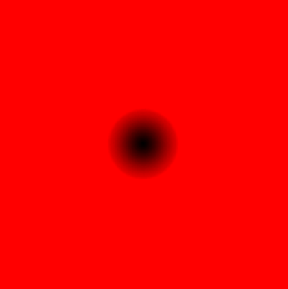
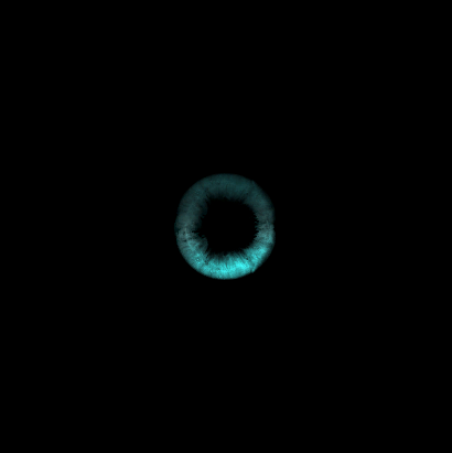
I like the use of BC4_UNORM here!
And if the AO+Alpha looks like “Normals” texture that’s fine, it’s not the texture mistake 😀 it’s the final composite of it’s 4 channels what makes it look like a normals texture!


At the end of that pass we draw particle systems, as mentioned earlier at section number 2. Those are the none emissive particles as well as the mesh particles.
Once particles are done, eventually, we end up with the 5 Render Targets (GBuffer) + the depth by the end of that pass.
Motion Vectors (Compute)
…
Deferred+ Lights (Compute)
…
Decals (4 RT + Dpth)
Before we talk about decals, let’s agree that on-characters effects are not projected as decals (blood, dirt, mud, snow,..etc.) and it is not taking place in that pass. As a matter of fact, those are done in the main color pass as part of the mesh shading & GBuffer creation.
For this color pass we do slight modifications on what been resulted from the previous pass. Perhaps the most notable thing here (i’ll be using a different capture to show it) is that we do another layer of snow deformations, but this time it is not that complex or involving any compute, just usual decals. Snow decals are coming in many forms in here, some are used to add a some snow fade (color) at the edges of objects
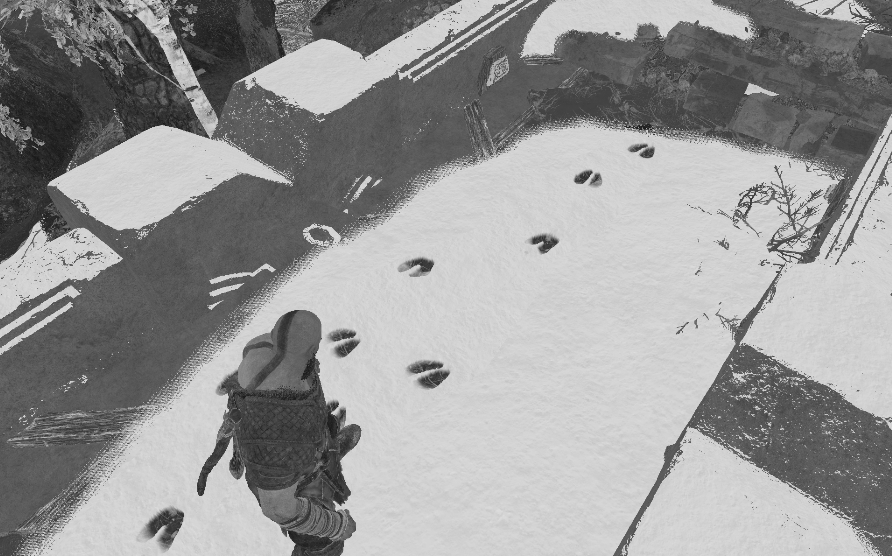
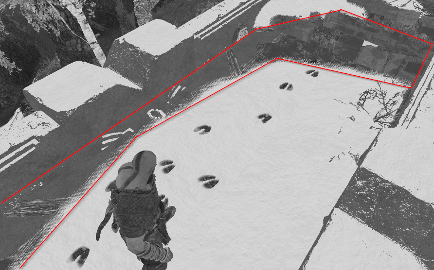
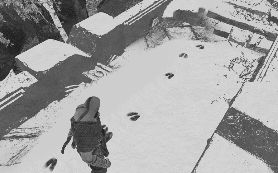
Where others are to project a to the final world normals using normal map texture such as the foot prints (there are different ones, i guess per character size) on the walkable snow surfaces.
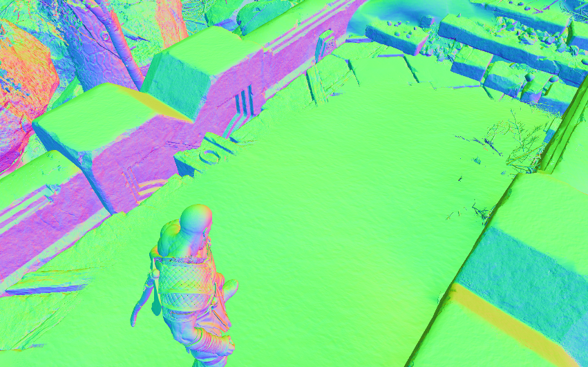

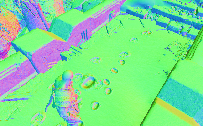
Different decal textures for different characters and use cases


There are decals that are placed in there, by level artists and designers as part of the level/area when loaded, for story reasons and whatnot. Things such as the deer footprints. this is already in there. But there are things that are placed at runtime during gameplay, like Kratos’s and Atreus’s footprints. But all in all, all decals are projected using simple cube meshes that are drawn one by one to the previous pass outputs (color, normal,..etc.).

Where is my BOY?
One thing to mention before leaving the decals. Where the deer foot prints are DrawIndexedInstanced, the decals for Kratos & Atreus are just DrawIndexed, and that’s the case for many decals. which makes no sense, the deer has only single decal around, may be few within the entire map, but the feet of the player and the npc are allover the place, wouldn’t it be better if they’re instanced too? or may be not and it is enough to be drawn because 1st there count vary all the time, 2nd those “may be” will vanish overtime?
6.Forward+ (Compute)
…
Forward Plus Compute Data (Click to open)
| Data | Type | Size/Dimensions | Format/Components |
|---|---|---|---|
| Forward Plus Compute Data | Constant Buffer | 16 bytes | forwardPlusComputeData { uint enableRadianceOutput; float outRadianceEmissiveIntensity; } |
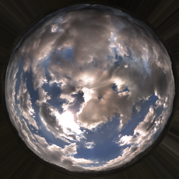
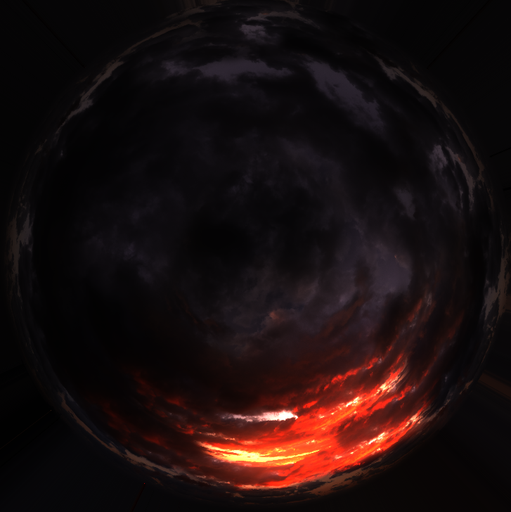
7.Skybox/Cubemap
Skyboxes in GoW are drawn just after the Fwd+ data been calculated (we got out the diffuse lighting), and right before we go into the GI and SSAO and the rest of the pipe. It is very simple, always the same, but with a different texture to fit the current mode. A simple hemisphere shape drawn at first (sorry to disappoint you, the skybox is not a box shape or the cubemap is not a cube shape in this game), and then textured with a 4096*4096 BC6_UFLOAT pretty texture that match the current realm/level. Those textures are of course in full range, and their A channel is full white.
The shader for the sky-pseudo-box, is also using a flow map, or better refer to it “flow direction” texture to do some cloudy animations, it is a 1024*1024 BC5_UNORM that utilizes only the RG channels (make sense, we flow in texture space, not world space) which usually not working alone. It takes a R8_UNORM alongside it as a flow mask. Yet, as far as i can tell, that flowmask texture was in use previously but not any more, kinda the technique been abandoned or something later (pre-release or on the PC version only), as the ones i found are always 1*1 which isn’t isn’t a viable mask as far as i can tell. But I’m still searching for examples of a valid flow mask in other game areas.


8.GI (Compute)
Unfortunately the GI in the PC version of GoW is not realtime dynamic. And it is baked GI/Lightmaps type of approach, in fact it came to me as a surprise when i knew that the initial 2018 release is not supporting dynamic GI at runtime and relying on baked GI, as during that time you could simply see other older games such as Assassin’s Creed Origins (2017) or Tom Clancy’s The Division (2016) (& the list goes on from mama Ubi and other companies) are using realtime dynamic GI while being bigger in the scope as Open World games and Crossplatform and not only single platform exclusive with limited vistas and well surrounded by mountains areas! Shame that this part didn’t get some love for the sake of PC,…but again, not my decision 😀
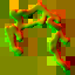
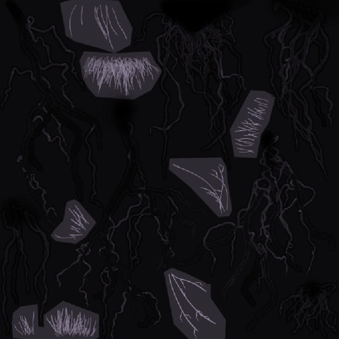
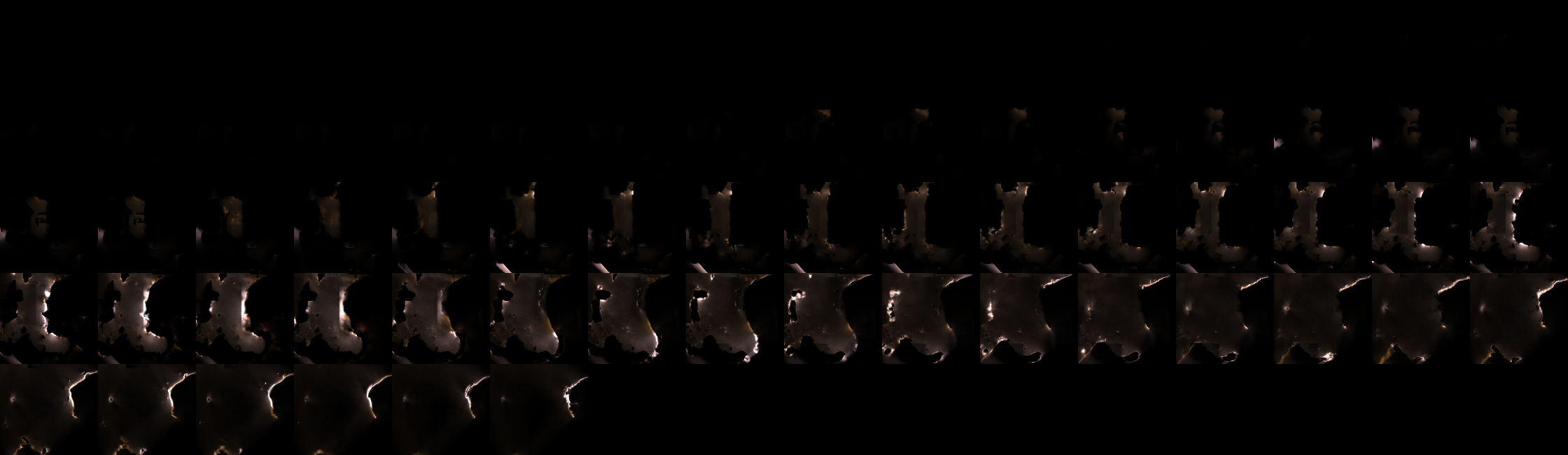
The GI bakes for GoW DX11 port are done in 3d textures in 32 slices usually (there are cases where bizarre number of slices that is not consistent with the rest of the game are used, things like 42 or 70 slices…!) for each one. Usually around 6 3d textures at least per area/level, all of them are in the format R16G16B16A16_FLOAT, but each map/area of the game vary in the 3d texture dimensions (W, H & depth). Some examples of GI bakes for some areas that I’ve visited.
First row is one of the bake 3d textures for the area, second row is the GI pass out, and last row is the final SWC.


The compute shader for the GI will always assume and hold the data (even if zeroed data) for total of 4 GI volumes. You can consider this as the maximum supported GI volumes per area. It could be made in better way, but it is what it is, 4 GI volumes data in memory even if you have only 2 volumes around.
Usually & most of the time there is 2 active GI volumes that the shader consider, sometimes there are 3 and rarely we have 4 active GI volumes at the same time. And of course, yet i did not meet any case where only single GI volume is utilized by the shader. You can sneak peak what GI volume type of data is fed to the compute from the expandable bar below.
GI Volumes Data
struct giVolumes
{
	int numGIVolumes;
	struct global
	{
		float giVolumeSHDiffuseBlur;
		float giVolumeSHSpecularBlur;
		float giVolumeSaturation;
		float4 defaultOcclusionSH;
		float4 skyFullRSH;
		float4 skyFullGSH;
		float4 skyFullBSH;
		float4 skyFullClampRSH;
		float4 skyFullClampGSH;
		float4 skyFullClampBSH;
		float4 skyFullGeoRSH;
		float4 skyFullGeoGSH;
		float4 skyFullGeoBSH;
		float4 skyTopRSH;
		float4 skyTopGSH;
		float4 skyTopBSH;
		float4 skyTopClampRSH;
		float4 skyTopClampGSH;
		float4 skyTopClampBSH;
		float4 skyTopGeoRSH;
		float4 skyTopGeoGSH;
		float4 skyTopGeoBSH;
		float4 skyTopAndBounceRSH;
		float4 skyTopAndBounceGSH;
		float4 skyTopAndBounceBSH;
		float4 skyTopAndBounceClampRSH;
		float4 skyTopAndBounceClampGSH;
		float4 skyTopAndBounceClampBSH;
		float4 skyTopAndBounceGeoRSH;
		float4 skyTopAndBounceGeoGSH;
		float4 skyTopAndBounceGeoBSH;
		float4 skyDifFullRSH;
		float4 skyDifFullGSH;
		float4 skyDifFullBSH;
		float4 skyDifFullClampRSH;
		float4 skyDifFullClampGSH;
		float4 skyDifFullClampBSH;
		float4 skyDifFullGeoRSH;
		float4 skyDifFullGeoGSH;
		float4 skyDifFullGeoBSH;
		float4 skyDifTopRSH;
		float4 skyDifTopGSH;
		float4 skyDifTopBSH;
		float4 skyDifTopClampRSH;
		float4 skyDifTopClampGSH;
		float4 skyDifTopClampBSH;
		float4 skyDifTopGeoRSH;
		float4 skyDifTopGeoGSH;
		float4 skyDifTopGeoBSH;
		float4 skyDifTopAndBounceRSH;
		float4 skyDifTopAndBounceGSH;
		float4 skyDifTopAndBounceBSH;
		float4 skyDifTopAndBounceClampRSH;
		float4 skyDifTopAndBounceClampGSH;
		float4 skyDifTopAndBounceClampBSH;
		float4 skyDifTopAndBounceGeoRSH;
		float4 skyDifTopAndBounceGeoGSH;
		float4 skyDifTopAndBounceGeoBSH;
	}

//regardless, we use 2, 3 or 4 GI Volumes, there will be always
an array with the size of 4 GI Volumes regardles.
	struct giVolumes[4]
	{
		struct giVolumes[0]
		{
			float3 invTransX;
			float3 invTransY;
			float3 invTransZ;
			float3 invTransT;
			float3 invRotX;
			float3 invRotY;
			float3 invRotZ;
			uint3 indDims;
			float3 invIndDims;
			uint3 atlasDims;
			float3 invAtlasDims;
			float4 cr1Min;
			float4 cr1MaxSubMin;
			float4 cr2Min;
			float4 cr2MaxSubMin;
			float4 cr3Min;
			float4 cr3MaxSubMin;
			float normalOffset;
			float4 giTintScaled;
			uint flags;
		}
		struct giVolumes[1]
		{
			float3 invTransX;
			float3 invTransY;
			float3 invTransZ;
			float3 invTransT;
			float3 invRotX;
			float3 invRotY;
			float3 invRotZ;
			uint3 indDims;
			float3 invIndDims;
			uint3 atlasDims;
			float3 invAtlasDims;
			float4 cr1Min;
			float4 cr1MaxSubMin;
			float4 cr2Min;
			float4 cr2MaxSubMin;
			float4 cr3Min;
			float4 cr3MaxSubMin;
			float normalOffset;
			float4 giTintScaled;
			uint flags;
		}
		struct giVolumes[2]
		{
			float3 invTransX;
			float3 invTransY;
			float3 invTransZ;
			float3 invTransT;
			float3 invRotX;
			float3 invRotY;
			float3 invRotZ;
			uint3 indDims;
			float3 invIndDims;
			uint3 atlasDims;
			float3 invAtlasDims;
			float4 cr1Min;
			float4 cr1MaxSubMin;
			float4 cr2Min;
			float4 cr2MaxSubMin;
			float4 cr3Min;
			float4 cr3MaxSubMin;
			float normalOffset;
			float4 giTintScaled;
			uint flags;
		}
		struct giVolumes[3]
		{
			float3 invTransX;
			float3 invTransY;
			float3 invTransZ;
			float3 invTransT;
			float3 invRotX;
			float3 invRotY;
			float3 invRotZ;
			uint3 indDims;
			float3 invIndDims;
			uint3 atlasDims;
			float3 invAtlasDims;
			float4 cr1Min;
			float4 cr1MaxSubMin;
			float4 cr2Min;
			float4 cr2MaxSubMin;
			float4 cr3Min;
			float4 cr3MaxSubMin;
			float normalOffset;
			float4 giTintScaled;
			uint flags;
		}
	}
}
I don’t agree with the struct alignment though…But who knows, if it works, then it works!!!
Let’s keep the fingers crossed, and wish that Santamonica try to do better at the GI aspect in the coming sequel of the game, while dynamic GI was doable on the PS4 hardware with some smart tricks, but defiantly the PS5 hardware is capable enough to do more without any compromises. Until we get hands on the Ragnarok, I highly recommend the GDC16 talk by Nikolay Stefanov of Ubisoft Massive about the neat Global Illumination in The Division. Links are by the end of the article…Oh boy, Snowdrop <3
SSAO
….
9.Emissive (& Late Particles)
There will be “always” 3 color render passes run near the end of the frame, the first one dedicated for global emissive uses, where the other two following are to draw more particles…the emissive ones. Each of those 3 passes consists of a 1 Target + Dpth. Regardless you’re in the main menu, casually walking around the world or in a brutal fight, those passes are always 3 and always near the end of the frame. (i might change my mind about that when i reach & take captures from Helheim..the realm of the dead)
Global Emissive (1 renderpass)
……
Emissive Particles (2 renderpasses)
……
10.Post Processing
Color Grading
Using a friendly looking 3d texture 64*64*64 of the format R10G10B10A2_UNORM and some values from the PostProcessing Data structure (in the table below) can have some slight color modifications to the overall frame.


ToneMapping, Bloom & Blur (FS)
the shader responsible for taking a half res version of the frame and apply the 16x sample blur as well as bloom
…
Temporal AA (Compute)
…..
To get a glimpse of what post processing takes place beyond the ones mentioned, or even the details of those ones I mentioned, below is a quick look into some of the data passed to the frag shader.
PostProcessing Data (Click to open)
| Globals | ToneMapping | DoF | TAA |
|---|---|---|---|
| constants { float MotionBlurEnabled, float DebugBlur, float DebugBlurEffect, float NoOpaquePass, uint DebugTakingCalibrationScreenshot, float DebugMotionVectors, float BloomEnabled, float2 screenSize, float2 screenSizeRcp, float2 screenHalfSize, float2 screenHalfSizeRcp, float2 screenSizeResolved, float2 screenSizeResolvedRcp, float2 screenResolvedToUnresolved, float2 screenUnresolvedToResolved, float2 motionVectorTemporalRescaleCompress, float2 motionVectorTemporalRescaleDecompress, float2 dlssScreenSize, float2 screenScale, float2 screenOffset, float4 scaleOffsetR, float4 scaleOffsetG, float4 scaleOffsetB, float3 Vignette_Color, float Vignette_Brightness, float Vignette_Falloff, float Vignette_Scale, float lensVignetteExposureSq, float scale,”0.96799″,float float rcpScreenLensRadius2, float2 screenLensCenter, int filmGrainOffset, float4 filmGrainUVTransform, float filmGrainEffectShadows, float filmGrainEffectMids, float filmGrainEffectBrights, float doUnsharp, float unsharpStrength, bool DebugNoLUT, bool passThrough, bool passThrough_Exposure, bool passThrough_WhiteBalance, bool passThrough_SLog } | toneMappingConstants { float3 WBMatrixR, float3 WBMatrixG, float3 WBMatrixB, float EnableLocalAdaptation, float Adaptation_Exposure, float ExposureEV, float ExposureEVClampMin, float ExposureEVClampMax, float LocalAdaptationShadows, float LocalAdaptationHighlights, int Tonemapping_Curve, float Contrast, float HDRMax, float HDRWhite, float ContrastTimesShoulder, float ChannelCrossTalk, float PrecomputedBMult, float PrecomputedCAdd, float SceneToScreenPower, float IsHDRRendering, float DebugHDRRendering, float DebugHDRRenderingPhase, float DebugNoHDRRendering, float ShowWaveform } | dofConstants { float m_Enabled, float m_DebugDOF, float m_NearDistanceOfAcceptableSharpness, float m_FarDistanceOfAcceptableSharpness, float m_CircleOfConfusionMultiplier, float m_CameraApertureHeightRelativeRcp, float m_HyperFocalDistance, float m_FocusDistance, float m_FStop, float m_DepthReprojectScale, float m_DepthReprojectBias } | temporalConsts { float TAAConvergenceLimit, float TAAHP, float TAALP, float TAAColorExtent, float TAACheckerboardFramePhase, float TAAMotionRejection, float TAAEnable, float HalfResTAAEnable, float HalfResTAAConvergence, uint TAAForceSmooth, float TAATransparentsContributionRejectionMultiply, float TAAVarianceBlurIncrease, float TAAVarianceTransparentDecrease, float TAAEncodeRange, float TAAInvEncodeRange, uint DebugSimilarity, float VarianceWindow, float2 UpsampleOffset } |
11. Post Processing 2 (at the UI renderpass)
Now this is tricky, Post processing happens in couple of passes. Where many of the post processing takes place in the previous step, at this phase and just right away before adding the UI to the frame, a vanilla new renderpass begins, this renderpass will be for both, the UI as well as a tiny bit of post processing. A lil FS runs on the output of the TAA to apply some FilmGrain & may be Vignette,…etc.. Also if there is DoF applied, that’s the right time to apply it as far as i can tell from the data passed to the shader at this moment.
If we’ve applied things such as Film Grain earlier before the TAA, the result of the TAA would reduce the Film Grain effect, this is why it need to be applied after the TAA, and where the TAA is done in the compute, we need another color renderpass to use the TAA outcome to apply any remaining postprocessings such as Film Grain. At the same time it might not be worth it to have an entire new renderpass for that, and hence i believe the choice came to apply the remaining postprocessing to the same renderpass where the UI gets drawn. Just to reduce the cost of launching & ending a dedicated renderpass for the Film Grain only.

And if it is hard to tell from the full frame
And of course that is done by using the simplest 512*512 BC4_UNORM single channel grain texture in the world.


Below at the end of this article, i’ve attached 2 in depth article’s links as an interesting reads from Timothy Lottes and Bart Wronski, regarding what i think the possibly used tonemapping technique in GoW.
12.UI
The thing i love about the UI in that game, is that pretty much everything (except the game logo so far from what i can tell) is built in the way i love. I do always love when UI elements are grayscale, this makes it easy to customize and fit the taste of the art director. I did saw some games would use a specific color of a specific UI elements, which is not something I’m big fan of. Almost every UI element in GoW is a BC4_UNORM (aka single R channel).


Drawing the UI is a sequence of DrawIndexedInstanced for rects in all sizes to fit the UI needs. So, by the end of that renderpass, we’ve the entire UI added to the frame, this is same renderpass used for the previous post processing, so it is single renderpass utilized for two purposes, PostProcessing + UI.
It is worth mentioning that, the UI shader seem very simple (well, it’s the case with most UI shaders anyways!), it takes aside to the group of grayscale textures a few other values for the alpha/alphaBlend, opacity, glow, edge glow, emissive, edge “burn”, side to side masking, a whole lot of values that are quite predictable what they do, below are the most common inputs for the UI shader/material
UI Material Data
struct UI_materialData
{
float3 Smoke_opacity_matU,
float3 Smoke_opacity_matV,
float3 Smoke_alpha_matU,
float3 Smoke_alpha_matV,
float3 edgeGlow_alpha_matU,
float3 edgeGlow_alpha_matV,
float3 edgeGlowBurn_alpha_matU,
float3 edgeGlowBurn_alpha_matV,
float3 Wipe_alpha_matU,
float3 Wipe_alpha_matV,
float pulse_cst_AlphaBlendAmount,
float Smoke_cst_AlphaBlendAmount,
float Smoke_cst_EmissiveIntensity,
float edgeGlow_cst_AlphaBlendAmount,
float edgeGlow_cst_EmissiveIntensity,
float BaseBurn_cst_AlphaBlendAmount,
float edgeGlowBurn_cst_AlphaBlendAmount,
float Mask_cst_AlphaBlendAmount,
float3 Mask_cst_EmissiveTint
}
I don’t agree with the struct alignment though…But who knows, if it works, then it works!!!
And of course, the more UI elements in the HUD, the longer the renderpass takes. I’ll leave you with this couple of timelapse of a UI renderpass from start to end for two of the game menus (the weapons menu & the map menu).


13.Gamma Correction
In this last call before we do present to the Swapcahin, this is a simple FS that will run to apply the proper gamma, which is at this case 1.6f.

14.Present
A Swapchain (most of my captures were 1920*1200 at my main PC, but for this example i used my other PC with 1920*1080) with the format DXGI_FORMAT_R10G10B10A2_UNORM & the usage D3D11_USAGE_DEFAULT & both bind flags D3D11_BIND_SHADER_RESOURCE and D3D11_BIND_RENDER_TARGET, is the final presentation. But the interesting thing here is that the swapchain have the flag DXGI_SWAP_CHAIN_FLAG_ALLOW_TEARING…this means the sync interval is probably set to 0 aka vsync is disabled, and yes, that’s the case, it is disabled by default in GoW unless you enable it. When vsync is disabled, this has pros and cons, but the main thing to mention here, that it impact the enable of Variable refresh rate (which is Windows10 only feature if i’m not mistaken). You can read more about this feature at the links at the end of the article.
Now come to the fun part, and the reason i wanted to highlight the vsyc topic, the screenshots below is from the game while running in debug mode, you can see when the Vsync value in the game options is ON, actually the NVIDIA hardware reports it as Forced-Off while FPS is capped to ~60. At the other hand, when it is in the game options set to OFF, the NVIDIA hardware doesn’t show anything about it, which means it considers it ON?! Not only that, i reach ~160 FPS where it is clearly the FPS Limit in the game is set to max of 120FPS & it never get respected by the hardware :/ interesting!


So, is NVIDIA reporting it wrong? because i do expect if it is OFF to reach high FPS (but still, why not respecting the 120 from the game settings?), and when ON to be limited to 30 or 60 or whatever. I thought this might be some bug with the tools, but Nope, below is a video captured while toying with the vsync settings but this time alongside the intel HUD to show the vsync status as well as the current FPS.
Also, in another note, the Swapchain had the SwapEffect set to FLIP_DISCARD, using that type of SwapEffect means that with we don’t have to copy (copy of course has overhead) the content of the back buffer with every call to present. Instead, the entire back buffer[s] will be shared with the Desktop Window Manager (DWM) with no guarantee that the contents of each back buffer is preserved. All in all, that FLIP_DISCARD is really good choice and it makes things a little bit more efficient. This tiny value can be very tricky, as each type has pros and cons in terms of allowing other features or not, you can read more about that at the links by the end of this article.
Life of a Frame
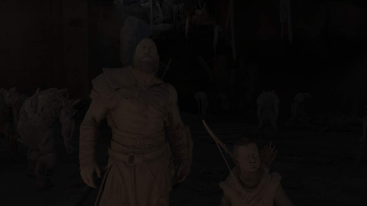
So, to put all in a semi-timeline visual format, here is a video showing the entire life of a frame (that frame was 19,219 event). The wonder here when you think about it, this sped-up 6 minutes video of all the rendering steps, GoW’s renderer is able to create 60 of it at least every SECOND! what a great era of GPUs we’re living in today!
Its Okay to see things repeated, kids become adults & outputs becomes inputs, it’s how life goes!
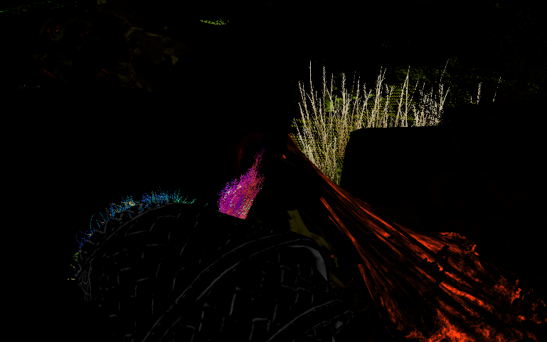
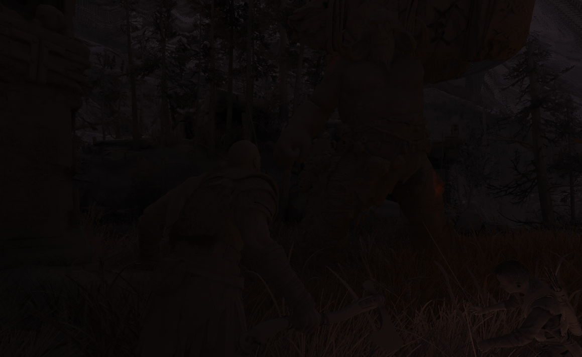
Keep in mind, when you see a sloid black or solid color for a while, this is most likely a compute running in the background, unfortunately we can’t see the progress of the compute i here, only solid color. Also when you see depth or something for quite sometime, don’t think it is frozen, nah, there are a lot of things added in the background, could be a tiny piece of grass or a bush behind Kratos. Check the other frame below, it uses a different method to show as much as possible of what is going on.
Random Notes
- GoW rendering in Double Buffering (i believe it is the case with many D3D11 titles).
- The color passes that present are rendered to a triangle that is larger than the display size, not a full screen quad, which is something i like to do, and it is what i made for Mirage. So i appreciate that thing in GoW!
- Atreus (possibly other NPCs, need to check further) are fully rendered when outside the view. I was expecting only his entity & gameplay data is exist without being fully rendered. But that’s not the case, in several captures where he is not around, he been drawn.
- Kratos’s beard is epic, because it is made of ~6 layers (may be more, i can’t remember the exact number). But in general the hair/fur always similar case, for example Kratos’s holster/armor thing around his chest have similar geometry layers count. At the other hand, a furry creature, like the pretty blue-eyed deer that Atreus was hunting, had ~14 layers of hair geometry around it’s entire body.
- It is also worth mentioning one consistent bizarre case. At the same color pass where the spheres are drawn to the snow deformation render target (this is off screen), there is ALWAYS a draw to the Leviathan Axe mesh at that offscreen. Why? I can’t really tell! But could be related to the axe’s functionality and the re-call thing that impacts the environment!? Not quite sure, but this one case is worth deeper investigation with more specific captures.
- There are few cases of attachments for X renderpass that are not used, but they are just in there. Those are not always in full final resolution (at my case 1920*1200), but at some cases are 1/2 of that (at my case 960*600). If that’s really not in use, and no actual reason for their existence, it’s then a nice area for improvement. I can be worng, nobody can judge any development choices except who made them, so those might be left in there for a reason.
- Pretty much most of the offscreen work done on a power of two rendertargets not in display size or downscale of the display size. Again, most of them, not all. There are defiantly still several offscreen rendertargets that runs either in display size or even very strange sizes that is not power of 2.
- Where mostly when we clear rendertargets, we clear to black, but there is few rendertargets in GoW that clears to Orange, where others clear to Green. I do love Orange, I do lover Purple & Gray. But i never thought about clearing my rendertargets to any of those colors..But I’ve got inspired 🙂
Epilogue
God of War is not only a great game with a great story and a PS4 hit, but also it have always been since the initial release a technical masterpiece and great wonder for any game engine and/or rendering enthusiast. What i said above is only my point of view of reading many GPU captures and trying to connect the dots and reverse the frames to better understand them & some of the decisions been taken about architecting them, so take it with a grain of salt.
I do love GoW franchise & Kratos since Jaffe’s creation, i might not had the chance to work in any of them, i might not had the honor to work on the 2018 version that have a special place in my heart, but at least now i had the pleasure to honor a game i like in the only way i can, by looking deep into the core of it’s heart.
At the end, i want to leave you with a link to a post of my favorite personal gaming collectable, and guess what, it’s for GoW 2018
-m
Related Readings & Videos
There you go:
– GDC Vault – Wind Simulation in ‘God of War’
– GDC Vault – Interactive Wind and Vegetation in ‘God of War’
– GDC Vault – The Future of Scene Description on ‘God of War’
– GDC Vault – Disintegrating Meshes with Particles in ‘God of War’
– GDC Vault – Global Illumination in ‘Tom Clancy’s The Division’
– Advanced Techniques and Optimization of HDR VDR Color Pipelines
– Localized tonemapping – is global exposure and global tonemapping operator enough for video games?
– Variable refresh rate displays
– DXGI_SWAP_EFFECT enumeration
– DXGI_FORMAT
– Block Compression (Direct3D 10)
Final Note
2022/02/15
While i wanted this to be an ongoing ~6 months project, and relaxly play the game without a rush & inspect every inch of it, but it came to an unexpected end (there is even a draft for part 2 about streaming, loading,…etc. I won’t be able to publish this). As a final note, while wrapping up that project files, i figured out why my drive’s partition started to give warnings about the remaining disk space! I’ll leave you with one final screenshot, of the total amount of data i’ve for that article after putting all of them now in their own final RIP folder!

-m